In a previous post titled Knowm Memristor Modeling and Simulation, I presented the implementation of a Verilog-A version of the Knowm MSS model within industry standard commercial EDA tools. Today I’ll be discussing the Knowm Open-Source EDA Stack that includes Knowm contributed extensions to popular open-source EDA tools to be used for the design, layout, and simulation of memristor devices and neuro-memristive circuits. This post will cover the installation and use of Schematic Capture and Circuit Simulation tools. I will provide a brief tutorial of Qucs – Quite Universal Circuit Simulator which is an open-source circuit simulator being developed by The Qucs Development Team – a multi-disciplinary group of talented engineers, scientists and mathematicians. This software is available on Sourceforge or Github for download under the GNU General Public License (GPL) v2+. The Qucs Team has developed a specific branch of the open-source project Qucs-S Spice4qucs to support several popular SPICE compatible simulators. This branch is being used to develop Knowm’s extensions to allow using the Xyce Electronic Simulator developed by the Xyce Team at Sandia National Labs. A new behavioral memristor model, the Knowm M-MSS ( Mean Metastable Switch Memristor Model ) was recently added to Xyce by Tim Molter and Alex Nugent. The Knowm M-MSS model is included in the Xyce OpenModels library and the model and Knowm’s release of Xyce-6.6 are both available under the GPL v3 open-source license. See the details of the implementation of the model in the recent post titled The Mean Metastable Switch Memristor Model in Xyce. Selection of this model is included from the new Xyce Memristor Technology library within Qucs-S along with the Known proposed new memristor symbol in the Qucs-S non-linear component library.
Knowm Memristor Symbol
Prerequisites
The current release candidate for the Knowm OSS EDA Stack is available for macOS Sierra 10.12 and Ubuntu 16.04 LTS (Xenial Xerus). This post covers installation on MacOS and Linux but usage only on the macOS platform. The installation process is different, but the use of the software is more or less the same. There is currently support for Xyce (Serial) simulations. The included versions of Qucs-S (0.0.19S) and Xyce 6.6 include libraries for amd64 (intel) 64-bit architectures. Support for other architectures and operating systems are under development and will be released when available.
Software Installation
First, download the pre-built bundles for the Qucs-S and Xyce for your operating system. These binary packages are available here:
MacOS Sierra
Install Qucs-0.0.19S bundle
- Double click on the bundle
qucs_knowm_oss_eda-0.0.19s-rc1.dmgto mount the bundle. -
Copy or drag-n-drop the
qucsfolder to/Applicationsfolder. -
Open the
qucsfolder that you just copied and open the./binfolder. -
Drag the
Qucs.appto the Launcher Bar. -
Right click on the Qucs-S bundle and select
Eject Qucs-Sfrom the context menu.
Install Xyce-6.6-Open_Source bundle
-
Double click on the bundle
xyce_knowm_oss_eda-6.6-rc1.dmgto mount the bundle. -
Copy or drag-n-drop the
xycefolder to/Applicationsfolder. -
Right click on the Xyce-6.6 bundle and select
Eject Xyce-6.6from the context menu.
Linux
NOTE: The release candidate Debian packages are currently being installed in the /usr/local under their own package directories to allow for side-by-side comparison of release candidates. The final release versions will be provided under a package manager and will use standard directories in /usr.
Install Qucs-0.0.19S .deb package
- Download the package
qucs-knowm-oss-eda-0.0.19s-rc1.debto the$HOME/Downloadsdirectory. -
Install using
dpkgthe following command $sudo dpkg -i qucs-knowm-oss-eda-0.0.19s-rc1.deb -
Set the PATH variable
export PATH=/usr/local/qucs/bin:$PATH -
Test the install by typing
qucs --version. -
Execution should return
Qucs 0.0.19 (7526999).
Install Xyce-6.6-Open_Source bundle
-
Download the package
xyce-knowm-oss-eda-6.6-rc1.debto the$HOME/Downloadsdirectory. -
Install using
dpkgthe following command $sudo dpkg -i xyce-knowm-oss-eda-6.6-rc1.deb -
Set the LD_LIBRARY_PATH variable
export LD_LIBRARY_PATH=/usr/local/xyce-6.6/serial/lib -
Set the PATH variable
export PATH=/usr/local/xyce-6.6/serial/bin:$PATH -
Test the install by typing
runxyce -v.
Launch Qucs-S
-
Click on the Qucs app icon on the Launcher Bar.
NOTE: the first time Qucs is started is will inform you that no default simulator has been selected.
-
Click
Okand then selectXyce (Serial)as the default. -
Click the
Selectbutton to the right of theXyce executable locationedit field. -
Select
runxycefrom the file browser and then clickOpen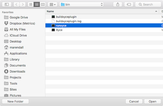
Default Simulator Settings
-
Click
Apply changes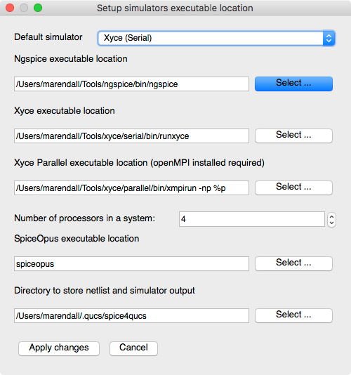
Default Simulator Selection
Qucs Application Settings
The Qucs Settings file qucs.conf is stored in your $HOME directory in the .config directory. If you experience any issues with persistence of your settings in this section you can manually edit this file with a compatible editor.
- Select
File->Application Settings...from the menu. -
Click the
Locationstab.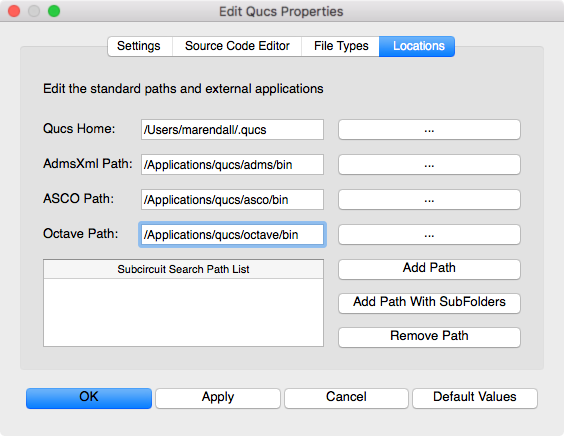
qucs app settings
NOTE: The Qucs Home will a folder named .qucs in your home directory. This is where all projects will be stored for your installation. Each project will be stored in a separate sub-directory with the _prj suffix appended to the name you specify. Other directories such as the spice4qucs directory will also be created which will store the data and netlist information for your Xyce simulations.
ADMS – Automatic Device Model Synthesizer
ADMS is a code generator that converts electrical compact device models specified in high-level description language into ready-to-compile C code for the API of SPICE simulators. Based on transformations specified in XML language, ADMS transforms Verilog-AMS code into other target languages.
- Verify
AdmsXml Path:is to/Applications/qucs/adms/bin. If not, set it.
ASCO – A SPICE Circuit Optimizer
ASCO project aims to bring circuit optimization capabilities to existing SPICE simulators using a high-performance parallel differential evolution (DE) optimization algorithm. Currently out-of-the-box support for Eldo (TM), HSPICE (R), LTspice (TM), Spectre (R), Qucs and Ngspice exist.
- Verify
ASCO Path:to/Applications/qucs/asco/bin. If not, set it.
GNU Octave – Scientific Programming Language
Powerful mathematics-oriented syntax with built-in plotting and visualization tools. The Octave syntax is largely compatible with Matlab. The Octave interpreter can be run in GUI mode, as a console, or invoked as part of a shell script. It is accessed in Qucs by selecting View->Octave Window.
- Set
Octave Path:to/Applications/qucs/octave/bin. If not, set it.
NOTE: Octave is not currently provided with this release. You can install Octave 4.2.0 from Homebrew tap homebrew/science
Save Application Settings
- Click
Applyto save the settings. -
Click
OKto exit the settings dialog.
Create a Project File
-
Select the
Projectstab on the left of the Main Dock. -
Click
Newto create a new project. -
Enter
Ymemristorfor the project name. -
Click the
Createbutton to create the project.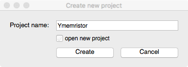
Qucs New Project Dialog
NOTE: The project
Ymemristor_prjis displayed in theProjecttab. -
Double click the
Ymemristor_prjto automatically open theContenttab.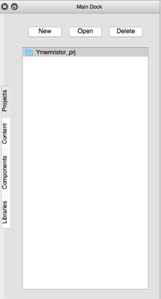
Qucs Project List
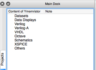
Qucs Project Contents
Create the Schematic diagram
-
Select the
Componentstab in the Main Dock. -
Open the
sourcesfrom the drop-down list. -
Select the
ac Voltage Sourceand then left click on the schematic to place the symbol. -
Press the
Esckey to exit place mode.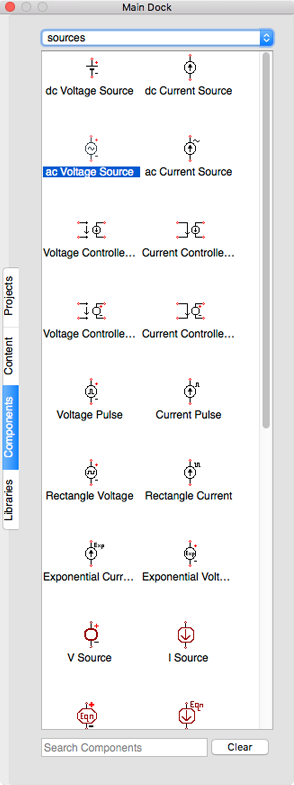
Qucs Component Sources

AC Voltage Source
-
Open the
non-linear componentsfrom the drop-down list. -
Select the
MR Memristorand then left click on the schematic to place the symbol. -
Press the
Esckey to exit place mode.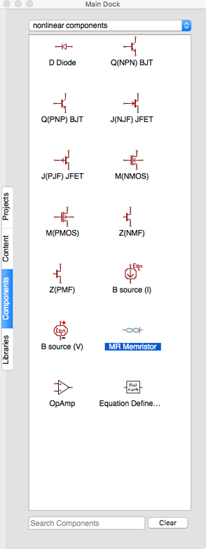
Non-linear Components Selection
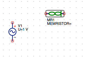
Components MR1 Memristor
-
Open the
probesfrom the drop-down list. -
Select the
Current Probeand then left click on the schematic to place the symbol. -
Press the
Esckey to exit place mode.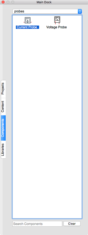
Component Current Probe
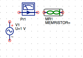
AC Voltage Source, MR1 Memristor and Current Probe
SUGGESTION: Try to place each component’s nodes on the grid. You can either manually position the component using you mouse or right click on the component symbol and select
Set on Grid. -
Select the
Gndsymbol on the toolbar then left click on the schematic to place the symbol.

Gnd Toolbar Button
-
Click on the minus terminal of the
ac Voltage Sourceto place anotherGndsymbol on the schematic. -
Press the
Esckey to exit place mode.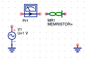
AC Voltage Source, MR1 Memristor, Current Probe and Grounds
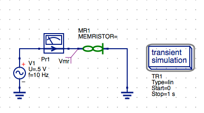
Set AC Voltage Source properties
-
Double click on the
ac Voltage Sourcesymbol to open the parameters for the source. -
Select the
Urow in the properties table. -
Change the voltage from
1 Vto500 mV. -
Click
Applyto set the voltage value.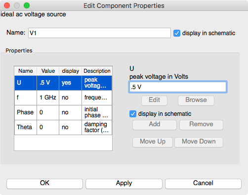
AC Voltage Source Settings
-
Select the
frow in the properties table. -
Change the
frequencyfrom1 GHzto10 Hz. -
Select the
display in schematiccheckbox.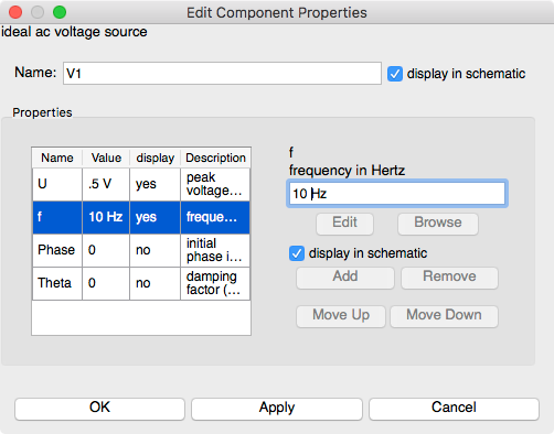
AC Voltage Source Frequency Setting
-
Click
Applyto set the frequency value. -
Click
OKto exit the properties dialog.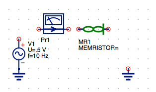
AC Source Voltage and Frequency Set
Wire the Schematic Components
-
Select the
Wiretool button on the toolbar.

Wire Toolbar Button
-
Select the free
Gndnode and then left click the negative node of the memristor symbol. -
Press the
Esckey to exit place mode. -
Select the positive node of the
ac Voltage Sourceand then left click the input node of theCurrent Probe. -
Select the out node of the
Current Probeand and drag to the positive node of theMR Memristor.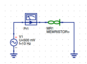
Wired Components
Add a Named Node (Vmr) to MR1 Component Positive Port
-
Click the
Namebutton on the toolbar.

Named Node Toolbar Button
-
Left click on the positive node of the
MR1 Memristorsymbol. -
Enter the
Vmrfor the label.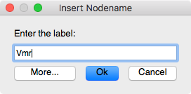
VmrNamed Node -
Click
OKto save the changes. -
Press the
Esckey to exit place mode. -
Click on the
Vmrlabel and drag it to a position below the memristor symbol. -
Left click on the schematic to exit
movemode.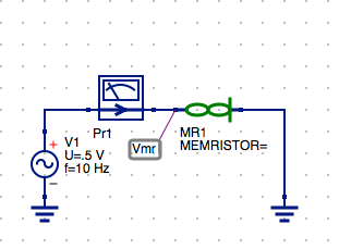
Named Node
Vmr
Clean up component and set MR Memristor parameters
-
Right click on the
MR Memristorsymbol and select theMove Component Textfrom the context menu. -
Left click on the
MR1 MEMERISTORlabel and drag it to a position below the memristor symbol. -
Left click anywhere on the schematic to exit
movemode.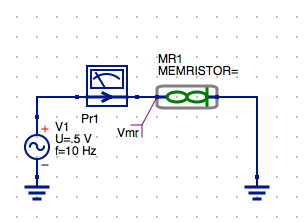
Move Component Text for MR1 Memristor
Configure the Transient Simulation of the MR1 Memristor Model
-
Select the
Componentstab from the Main Dock. -
Open the
simulationsfrom the drop-down list. -
Click and drag the
Transient Simulationand drop it on the schematic and left click to place the symbol. -
Press the
Esckey to exit place mode.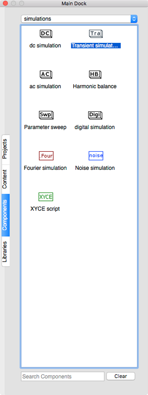
Component Simulators Selection
Transient Simulation
-
Double click on the
transient simulationsymbol to open the setup parameters dialog. -
Enter
500 msin thestopparam field. -
Enter
101in the number value field to set a 10 ms step size.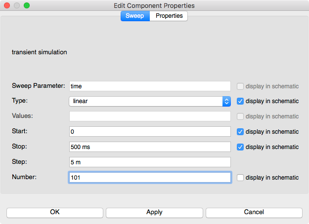
Transient Simulation Settings
-
Click
Applyto save the changes. -
Click
OKto exit the properties dialog.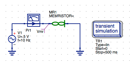
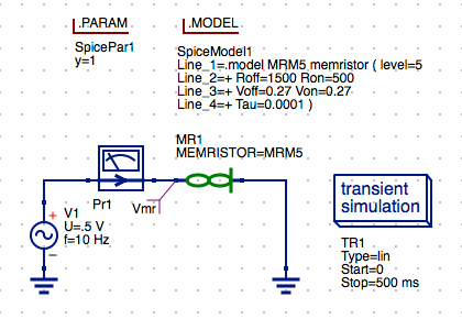
Transient Simulation
Select the .Model Directive for the MR Memristor Component
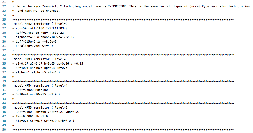
The MR Memeristor model is accompanied by several model directives that can be independently
applied to each memristor symbol instance in the schematic diagram. These are selected from the
Libraries tab. The MR Memristor component is used for multiple model definitions in Xyce. These
are selected by the level parameter of the model. The following levels are available for the
MR Memristor model in Xyce.
The parameters sets are stored in the .Model card format for SPICE compatible simulators.
level=2 : TEAM memristor model
level=3 : Yakopcic memristor model
level=4 : Joglekar memristor model
level=5 : Knowm M-MSS memristor model
Xyce Memristor Technology Lib
NOTE: Each of these correspond to the model parameter sets above can be selected by choosing from the available models in the Xyce Memristor Technology Library. The selection .Model and assignment to the MR1 Memristor component in the schematic determines the the model being simulated.
- Select the
Librariestab from the Main Dock. -
Left click on the
Xyce_Memristor_Technologyto expand the list.Notice: there are 4 different levels for the Memristor Model in Xyce. Each of these correspond to the model parameter sets above.
-
Select the appropriate
MRM(X)file for the model you want to use. In this caseMRM5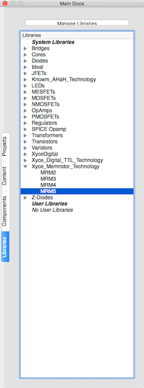
Xyce Memristor Knowm MSS Model (MRM5)
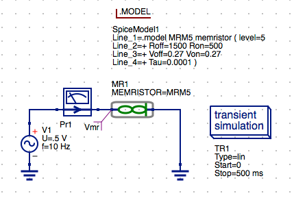
Knowm Memristor .Model Directive
-
Left click to place the .Model directive on the schematic.
-
Press the
Esckey to exit place mode.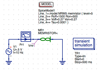
Knowm MSS Memristor Model
Select the model for the MR1 Memeristor component
-
Double click on the
MR1symbol to open the setup parameters dialog. -
Select MEMRISTOR line 1.
-
Enter
MRM5in the param list and model spec field.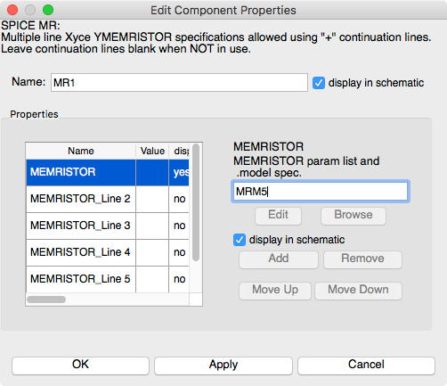
MR1 Memristor Settings
-
Click
Applyto save the changes. -
Click
OKto exit the properties dialog.
MR1 Memristor Defined as MRM5
Configure the Rinit .PARAM for the MR Memristor Model
-
Select the
Componentstab from the Main Dock. -
Open the
SPICE specific sectionsfrom the drop-down list. -
Click and drag the
.PARAM Sectionand drop it on the schematic and left click to place the symbol. -
Press the
Esckey to exit place mode.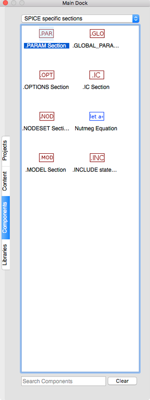
Components SPICE Specific
SPICE .Param Component
-
Double click on the
.PARAMsymbol to open the setup parameters dialog. -
Enter
Rinitin the param field. -
Enter
500in the value field to set Rinit=500 ohms.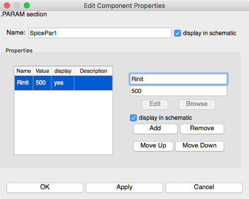
.PARAM Rinit Settings
-
Click
Applyto save the changes. -
Click
OKto exit the properties dialog.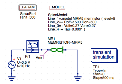
RInit .PARAM Directive
Set Document Settings (Optional)
For smaller sized schematics it is often desirable to add the data tables and plots to the schematic
diagram. The default behavior is for the data to displayed in a separate tab after the simulation is
complete. You can change this behavior by changing the settings for the schematic diagram.
- Right click on the schematic and select
Document Settings... -
Select
Simulationstab. -
Uncheck
open data display after simulationcheckbox in the dialog.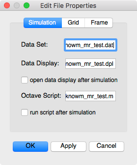
Current Document Settings
-
Click
Applyto save the changes. -
Click
OKto exit the properties dialog.
Save the Schematic Diagram File
-
Click the
Savebutton on the toolbar.

Save Toolbar Button
-
Enter the filename
knowm_mr_testfor the schematic diagram. -
Click
Saveto save the schematic to the.schfile.
Set Keyboard Preferences (Optional)
-
Open
System Preferencesand selectKeyboard. -
Then check thebox
F1,F2,etcas standard function keys.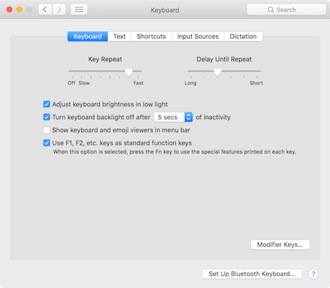
Change Keyboard Preferences for F1, F2 Selection
NOTE: You can change the keyboard mapping for other the keys in macOS by selecting the
Shortcutstab then define the new key mappings in theKeyboardgroup.
Run a Simulation
-
Press
F2or selectSimulatefrom the Simulation menu or theRunbutton on the toolbar.

Run Simulation Toolbar Button
-
Check simulation for
errorsorwarnings. See the status bar at the bottom of the Qucs windowlower right corner.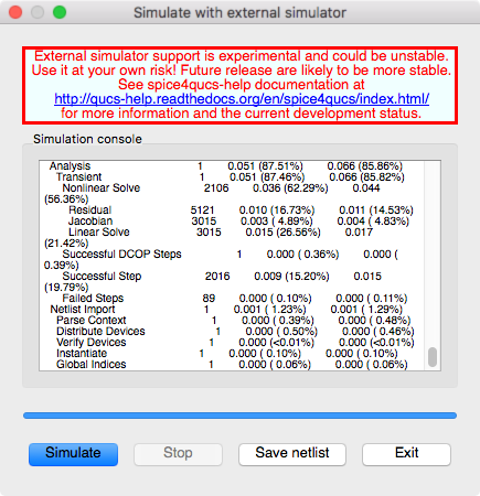
External Simulation Window
-
Click the
Exitbutton to close theSimulationwindow. -
You can view and messages written by the simulator by clicking the
F5key or selectingShow Last Messagesfrom the Simulations menu.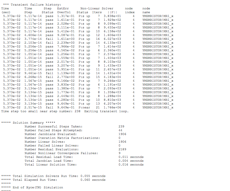
Xyce Simulation Messages
-
You can save the current netlist by clicking the
Save Netlistbutton on the simulation window.NOTE: The
F6key orShow Last Netlistfrom the Simulations menu currently only displays the last netlist for the lastestQucsatorsimulation. If you save the netlist using the button on the simulation window then you can open the.cirfile underOtherslist in the project tree.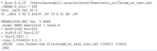
Qucs Generated Xyce Netlist
-
The raw data file
knowm_mr_test_tran.txtproduced by the transient simulation will be automatically created in the$HOME/.qucs/qus4spice/directory.
Check Tabular Results
-
Select the
Componentstab from the Main Dock. -
Open the
diagramsfrom the drop-down list.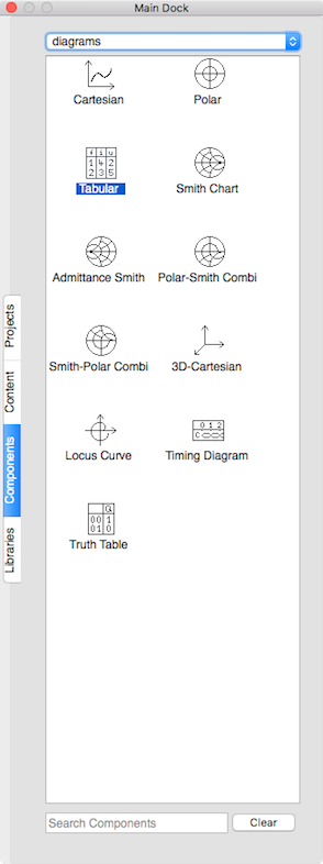
Component Diagram Tabular Data
-
Select the
Tabularand then left click on the schematic to place the table.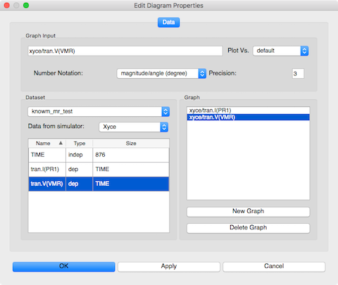
Diagram Tabular Data Settings
-
Double click on the
tran.I(PR1)row to add it to the graph. -
Double click on the
tran.V(VMR)row to add it to the graph. -
Click
Applyto set the value. -
Click
OKto save the changes.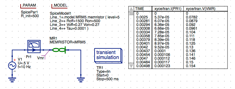
Tabular Data Display
-
Press the
Esckey to exit place mode.
Create a Memristor Current,Voltage vs. Time Plot
-
Select the
Componentstab from the Main Dock. -
Open the
diagramsfrom the drop-down list. -
Select the
Cartesianand then left click on the schematic to place the symbol.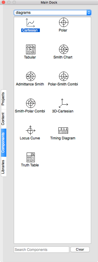
Component Diagram Cartesian Plot
-
Select
tran.V(VMR)row to add it to the graph.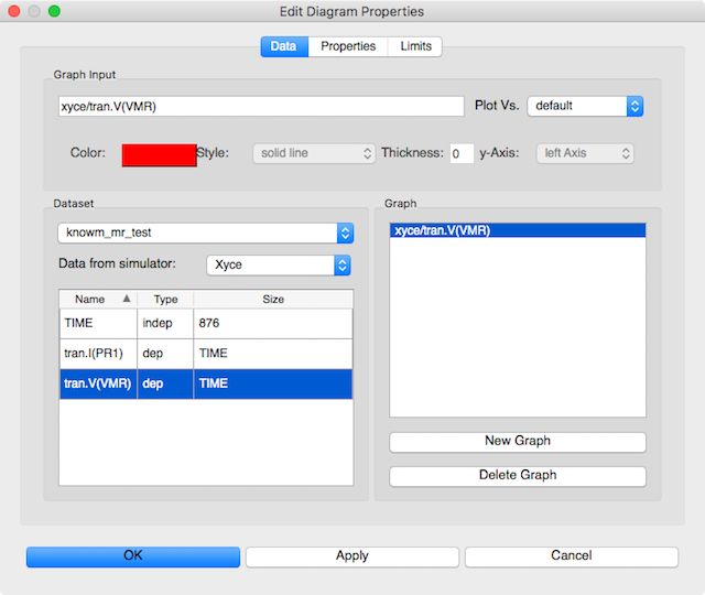
Diagram Cartesian Vmr Settings
-
Double click on the
tran.I(PR1)row to add it to the graph.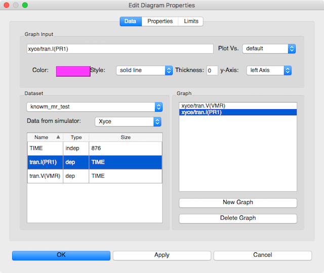
Diagram Cartesian Pr1 Current Setting
-
Select the
tran.I(PR1)in the Graph window. -
Select
right axisin they-Axis:drop-down list.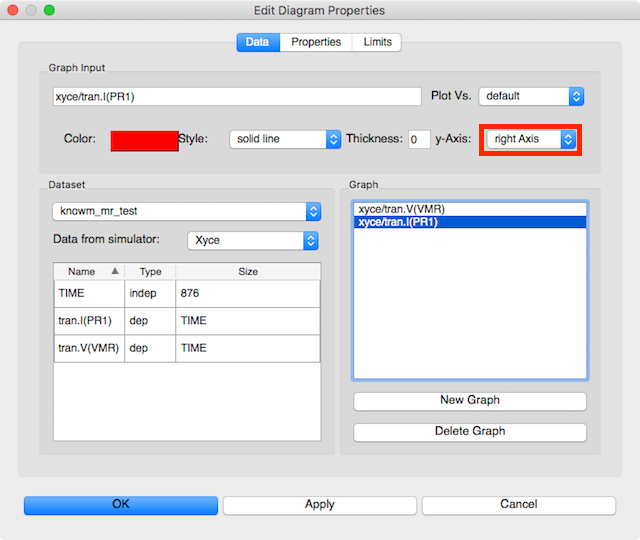
Cartesian I,V vs. Time Plot Settings
-
Click
Applyto save the changes. -
Click
OKto exit the properties dialog. -
Press the
Esckey to exit place mode. -
Left click anywhere on the plot window and use the corner grab handles to resize the plot.
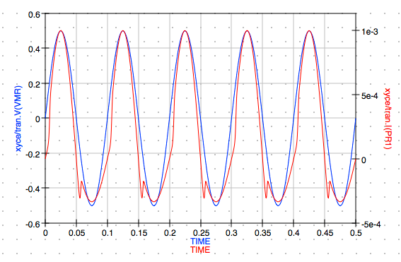
Cartesian I,V vs. Time Plot
Create a Hysteresis Plot
-
Select the
Componentstab from the Main Dock. -
Open the
diagramsfrom the drop-down list. -
Select the
Cartesianand then left click on the schematic to place the symbol.Component Diagram Cartesian Plot
-
Double click on the
tran.I(PR1)row to add it to the graph.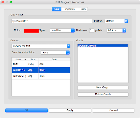
Cartesian Pr1 Current Setting
-
Select the
tran.I(PR1)in the Graph window. -
Select
tran.V(VMR)in thePlot Vs.drop-down list.Notice that the
Graph Inputchanges to xyce/tran.I(PR1)@tran.V(VMR)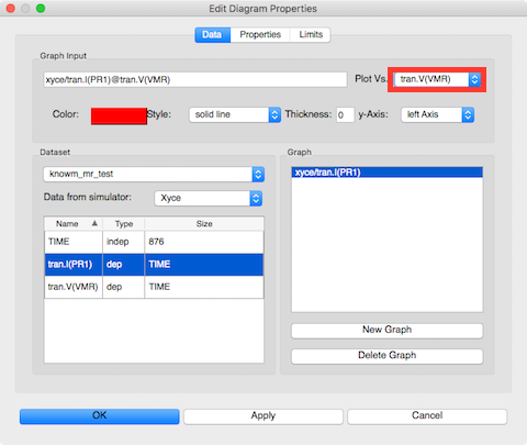
Cartesian I vs V Plot Settings
-
Click
Applyto save the changes. -
Click
OKto exit the properties dialog. -
Press the
Esckey to exit place mode. -
Left click anywhere on the plot window and use the corner grab handles to resize the plot.
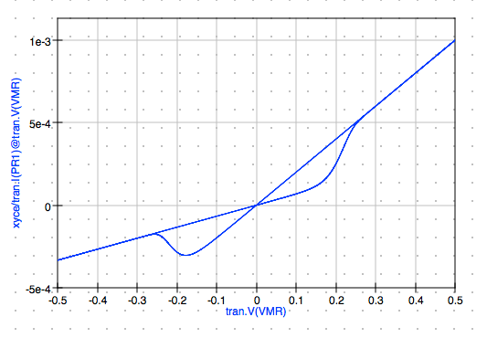
Cartesian I vs V Hysteresis Plot
That completes this basic tutorial.
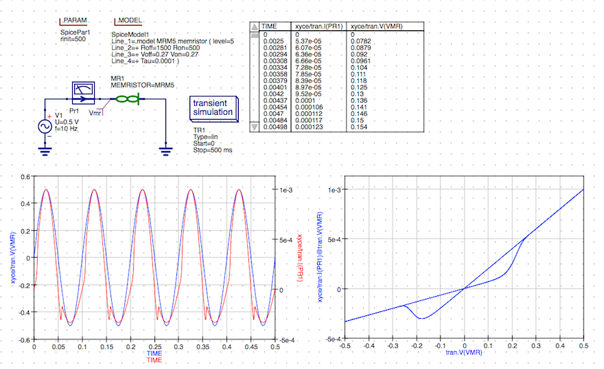
Transient Simulation Results
You should also checkout the documentation and other examples listed in the Qucs 0.0.19 and Qucs-S 0.0.19 documentation available on the web at the following URLs.
- Qucs 0.0.19 Help: https://qucs-help.readthedocs.io/en/0.0.19/subcircuit.html
- Qucs-S 0.0.19 Help: https://qucs-help.readthedocs.io/en/spice4qucs/SPICEComp.html
- Qucs-S Bugtracker: https://github.com/ra3xdh/qucs/issues
- Qucs-S Sub-project Home Webpage: https://ra3xdh.github.io/
Other References
- What is Qucs?
- What can all be installed from Sourceforge?
- Qucs Website: http://qucs.sourceforge.net/
- Main Repository: https://sourceforge,net/p/qucs/git/ci/master/tree/
- Mirror Repository: https://github.com/Qucs/qucs
- Mailing lists: http://sourceforge.net/p/qucs/mailman/
- Forum: http://sourceforge.net/p/qucs/discussion/
- Bug trackers:
- Source code documentation:
- Wiki: https://github.com/Qucs/qucs/wiki
Further Resources
- Knowm Memristors
- The Generalized Metastable Switch Memristor Model
- The Problem is Not HP’s Memristor–It’s How They Want To Use It
- The Joglekar Resistance Switch Memristor Model in LTSpice
- Build Xyce from Source for ADMS Verilog-A Model Integration
- The Pershin Voltage Threshold Memristor Model in NGSpice
- memristor-models-4-all Project on Github


3 Comments
JP
Dear, Thanks a lot for detailed procedure
Still one issue with library
INLINE with text. : On the Libraries tab from the Main Dock. Left click on the Xyce_Memristor_Technology
Ive nothing displayed just System & User ( if I click Manage Lib , I got an error Cannot start library Prog )
Maybe there is some missing params in the procedure ? Shall I ve to install native qucs, or only qucs_knomw package is enough ?
thanks in advance for any feedback JP
JP
Dears, Using OS X , I was faced to library issue ( not populated after fresh install )
One solution is just edit /Applications/qucs/bin/qucs (script file ) and change the /Applications/qucs/bin/qucs.app/Contents/MacOS/qucs
Lunch qucs by this script only and not by the Icon !
Regards, JP
JP
Thanks a lot for the details provided,
Ive tried on OSX Catalina but not working due to some script to align & links to create
Here is my advice to make it work under Catalina
1/ add export DYLD_LIBRARY_PATH=/Applications/xyce/serial/lib in .bash_profile
2/ change path in scripts /applications/qucs/bin/qucs (ie /Applications/qucs/bin/qucs.app/Contents/MacOS/qucs)
3/ create a icon pointing to this script/applications/qucs/bin/qucs ( not using global App icon !!! other library will not work)
4/ add following symbolic link
cd /usr/local/opt/suite-sparse/lib/
ln -s libumfpack.5.7.9.dylib libumfpack.5.7.6.dylib
cd /usr/local/opt/suite-sparse/lib/
ln -s libcholmod.3.0.14.dylib libcholmod.3.0.11.dylib
cd /usr/local/opt/suite-sparse/lib/
ln -s libsuitesparseconfig.5.7.2.dylib libsuitesparseconfig.4.5.5.dylib
Enjoy !
( Thanks Alex & Michael for your support)