Read part 1 of this series here
Private Beta Ahoy!
Well, I certainly did not expect to get the attention that part one of this blog series received! People have reached out from around the world, some already asking when the product will be available, others eager to know where they can start learning about memristors. The more I work on this project the more I realize how much it’s needed, especially now in the time of COVID-19 when so many teachers and students are locked out of their labs. Knowm.ai memristor array web service here we come! Between packaging chips, designing, populating and testing the PCB boards, programming the server and the (two) client libraries, setting up the networking, and all the rest I have yet to blog about–I have to say this has been one heck of an undertaking. Regardless, the thrill of seeing everything come together is a reward in itself, and of course it’s wonderful hearing from people around the world.
Fixing the Driver Bias
As per my last post I discovered a ~65mV bias voltage on the driver, which I still needed to fix. The bias was caused by my failure to provide a negative voltage supply for one of the driver amplifiers. This was a dumb omission on my part, and I am surprised memristor programming worked so well in spite of the bias–the negative erase threshold for the M+SDC devices is typically in the .05 to .1V range, almost exactly equal to the bias!
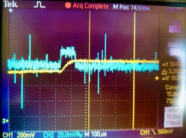
Bias in pulse generator (blue trace) caused by lack of negative supply voltage on driver amplifier.
While I was lucky that it worked, I had to fix it. I had some room on the driver V1.2 PCB where I had put the Knowm logo, so I added a negative bias generator and snuck it into the V1.3 circuit without much fuss. Specifically, I used an LM7705 which provides a negative .232 voltage supply via a switched capacitor circuit. It was made specifically for this issue and, thankfully, it worked out well.
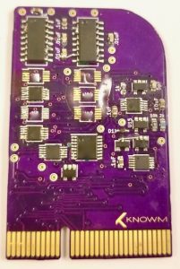
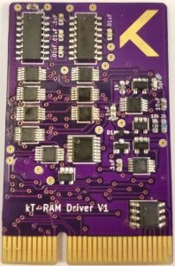
| Driver V1.1 | Driver V1.2 | Driver V1.3 |
|---|---|---|
 |
 |
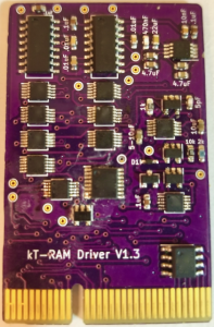 |
I am satisfied with the performance of the driver, both the pulse generators and sensing circuits. The plan is that driver V1.X is a half-core (unitary) driver, while V2.x will be full-core (differential) or half-core with a configuration option to choose. V2 drivers will contain more components but will be based on all the same base sub-circuits. V3 drivers will contain selectable options for current limiting while writing, for example the feedback ammeter circuit of Gomez et all, a programmable series resistor, or perhaps something else.
Cleaning up the Calibration Sensing Code
As I explained in part one, I decided to utilize a calibration chip to perform more accurate resistance/current sensing. While I was able to easily derive a theoretical equation that mapped the sense voltage to circuit current (and hence resistance or conductance), I found that component part variations and parasitic capacitance rendered the equation fairly inaccurate. To remedy the situation I used an array module and wirebonded some SMT resistors of known value to some of the rows/columns. I used the measured voltage-resistance values to linearly interpolate resistance values. This method was sufficient to get things rolling, but it left a lot to be desired, namely a linear interpolation was not very accurate for some voltage ranges and, probably the worst–I had an upper ‘cut off’ resistance that was determined by the resistances I used in the calibration chip. That is, the largest resistor I used was 499kΩ, limiting all readings past this to just read “499kΩ”. As our memristors can operate well past 500kΩ, I needed a better method to interpolate measurements.
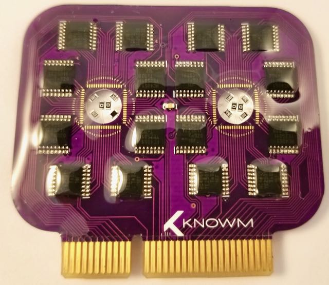
Calibration chip with SMT resistors in place of the memristor array
My solution is really what I should have done first, which was to use the calibration data to perform a quick multi-variable curve fitting to a simple equation (informed by the theoretical equation) and to use the curve fit for interpolation. Given a “Calibration Profile” that specifies the parameters of a read pulse, namely the (1) pulse amplitude, (2) pulse width, (3) pre-amp gain and (4) series resistor value, the fitted curve is stored and used to interpolate future read operations that use that profile. I went ahead and wrote code that will store these profiles to a file and load them during boot-up, which means that once I generate the profiles I never need to do it again, thus allowing the module slot to be used for memristors instead of the calibration chips.
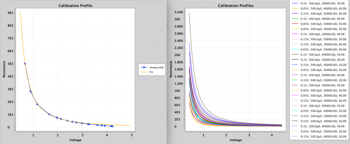
Calibration Profiles
As can be seen from the plots above, the curve fit is pretty good and within my OCD tolerance. The code I wrote to perform the curve fit is posted below for anybody interested. For any equation with a handful of variables it will work well. Nothing special, just brute force optimization. I will leave it as an exercise to the reader to understand what it’s doing. Probably the only thing worth explaining briefly is that it’s not really possible to get an accurate resistance measurement at both extremes (low or high sense current) using just one profile. A profile with a large gain and large series resistance will work better for low sense currents, while lower gains and smaller series resistances will work better for higher sense currents.
|
1 2 3 4 5 6 7 8 9 10 11 12 13 14 15 16 17 18 19 20 21 22 23 24 25 26 27 28 29 30 31 32 33 34 35 36 37 38 39 40 41 42 43 44 45 46 47 48 49 |
public void fitCurve(CalibrationProfile calibrationProfile) { float[][] calibrationData = calibrationProfile.getCalibrationData(); float[] parameters = calibrationProfile.getCurveFitParameters(); int n = 10; for (int i = 0; i < 256; i++) { float[][] tweaks = tweakParameters(.02f, parameters); parameters = evaluateParameters(tweaks, n, calibrationData); } calibrationProfile.setCurveFitParameters(parameters); } private float[][] tweakParameters(float p, float[] params) { int numTweaks = (int) Math.pow(2, params.length); float[][] tweaks = new float[numTweaks][params.length]; int clk = 1; boolean b = false; for (int i = 0; i < params.length; i++) { for (int j = 0; j < numTweaks; j++) { if (j % clk == 0) { b = !b; } if (b) { tweaks[j][i] = params[i] + p * params[i]; } else { tweaks[j][i] = params[i] - p * params[i]; } } clk *= 2; } return tweaks; } private float[] evaluateParameters(float[][] tweaks, int n, float[][] calibrationData) { float[] error = new float[tweaks.length]; for (int i = 0; i < error.length; i++) { float sumError = 0; for (int j = calibrationData[0].length - 1; j > calibrationData[0].length - n - 1; j--) { float vRead = calibrationData[0][j]; float r_actual = calibrationData[1][j]; float r_predict = CalibrationProfile.curve(vRead, tweaks[i]); sumError += Math.abs((r_predict - r_actual) / r_actual); } error[i] = sumError; } AveMaxMinVar stats = new AveMaxMinVar(error); return tweaks[stats.getMinIndex()]; } |
|
1 2 3 |
public static float curve(float v, float[] params) { return params[0] * (params[1] / (float) Math.pow(v, params[3]) + params[2]); } |
EEPROM
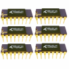
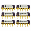
While EEPROM identification chips are standard practice I had never until this project actually used them (reason enough to try!). I figured it would be important to keep track of array modules over time, to have a unique identifier/serial numbers but also to store product information and perhaps even usage statistics that followed the module around. Knowm crossbars come in a number of variants, for example 32x32x1, 8x8x4, 4x4x8, etc. By programming the EEPROM on each module the board can identify what array module has been inserted into the port and load the appropriate driver code. While this is one example, if you really start to think about how useful it is to have a unique identifier and a small amount of memory available for each component over a shared I2C bus, you quickly realize the potential. I figured I would want to put these little beasties on everything from here on out, and if I was going to do that I had better write some scalable and reusable code to handle reading and writing the chips for anything I could dream up.

EEPROM All The Things!
In the Java world it’s standard practice to automatically map various data formats to “POJO’s”, i.e Plain Old Java Objects. Using reflection, it’s possible to programmatically interrogate a Java class to extract its members and data types. This is used, for example, in various Java libraries for automatically converting POJO’s to JSON and back again–something that is done ubiquitously in web application code. I figured I wanted the same thing for my EEPROM chips. Given a “ProductEEPROM” POJO object I wanted to automatically convert its fields to bytes and write them to the EEPROM, and visa versa–to read the bytes from the EEPROM and automatically instantiate a POJO object with the data.
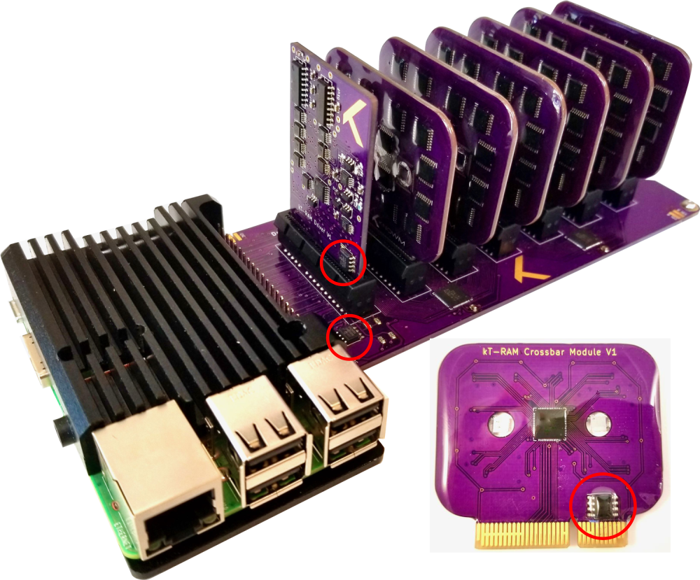
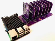
EEPROM Chips on all components of the kTPiServer
Converting to and from bytes is not really difficult. It’s possible to do this automatically with Java serialization. The difficulty is that using vanilla Java serialization is ridiculously inefficient because it keeps track of many more things than just the raw byte data of an objects fields. EEPOM memory is not exactly abundant, so I figured I would roll my own reflection code that performed the POJO<->EEPROM byte data mapping. This of course took a few days to code well, but I am generally happy with the result. I use the first couple of bytes to store a product id, which in turn is associated with a specific EEPROM_Product POJO. From there I use reflection to automatically read and write data to bytes making good use of the Java java.nio.ByteBuffer class. I will end this section with a call to KTRAMAdminClient.loadModules(hostURL), which satisfyingly returns the following thanks to the EEPROM.
|
1 2 3 4 5 6 |
Module 0: Memristor Crossbar Module V1 8x8x4 W+SDC, manufactured Fri Oct 02 15:09:35 MDT 2020, Two crossbar die with access circuitry in a dual 32x32 array module. Module 1: Memristor Crossbar Module V1 8x8x4 W+SDC, manufactured Fri Oct 02 15:09:57 MDT 2020, Two crossbar die with access circuitry in a dual 32x32 array module. Module 2: Memristor Crossbar Module V1 8x8x4 W+SDC, manufactured Fri Oct 02 15:10:06 MDT 2020, Two crossbar die with access circuitry in a dual 32x32 array module. Module 3: Memristor Crossbar Module V1 8x8x4 W+SDC, manufactured Mon Aug 17 21:29:25 MDT 2020, Two crossbar die with access circuitry in a dual 32x32 array module. Module 4: Memristor Crossbar Module V1 4x4x8 W+SDC, manufactured Sun Aug 30 12:31:29 MDT 2020, Two crossbar die with access circuitry in a dual 32x32 array module. Module 5: Memristor Crossbar Module V1 4x4x8 W+SDC, manufactured Wed Sep 16 15:29:42 MDT 2020, Two crossbar die with access circuitry in a dual 32x32 array module. |
User Accounts, Permissions, Array Usage Limits and a System Administrator
As a server architecture, I started to think about the near future where multiple people would be sharing access, for example a professor hosting the server in the lab and multiple students working from home, each with access to their own subset of memristor arrays. I implemented user accounts with a separate administration interface. Users can be created, given array privileges, and expirations dates set. Fairly basic stuff, but important if this is going to be deployed at any scale. As it exists currently, a user can be assigned to any subset of arrays across any of the modules by the system administrator. If a user attempts to access an array for which they do not have privileges, they will be denied access. For example, on the admin side we can issue a call to set permissions, KTRAMAdminClient.setUserPermissions("alex", "0-2", "*","*", true, adminHost). Assuming the user “alex” had no permission before the above call, he will now have access to all arrays over all units of modules 0, 1 and 2. This can be verified by a call to getUserPermissions("alex") which prints the following to the consol:
|
1 2 3 4 5 6 7 8 9 10 11 12 13 |
Module-ID Unit-ID | [array permissions] M-0 U-0 | [0] [1] [2] [3] M-0 U-1 | [0] [1] [2] [3] M-1 U-0 | [0] [1] [2] [3] M-1 U-1 | [0] [1] [2] [3] M-2 U-0 | [0] [1] [2] [3] M-2 U-1 | [0] [1] [2] [3] M-3 U-0 | 0 1 2 3 M-3 U-1 | 0 1 2 3 M-4 U-0 | 0 1 2 3 4 5 6 7 M-4 U-1 | 0 1 2 3 4 5 6 7 M-5 U-0 | 0 1 2 3 4 5 6 7 M-5 U-1 | 0 1 2 3 4 5 6 7 |
Each array that is enclosed in brackets indicates that the user has permission to access the array.
To prevent damage to arrays, either intentionally or more likely unintentionally, I implemented “usage limits” that can be placed on each array. Specifically, if the pulse amplitude exceeds the positive or negative limit or if the series resistor is lower than the limit, the operation will be denied. This is important, as a slip of the finger is all it takes to go from an intended .5V write pulse to a 5 volt write pulse, the later causing permanent damage. Yeah, I did that. Twice.
…a slip of the finger is all it takes to go from an intended .5V write pulse to a 5 volt write pulse, the later causing permanent damage. Yeah, I did that. Twice.
With user accounts and privileges comes separate projects for the Server, the User-Client and the Admin-Client, each with its code and documentation. This stuff just balloons fast doesn’t it?!
Networking
It’s one thing to host a server within your home network, but it’s another to provide a scalable public web service. I am by no means an expert at any of this, but I do understand enough to know that if I make any serious mistakes when I launch a public service I will get obliterated by hackers. For whatever reason, Knowm is the target of almost constant phishing and hacking attempts. Many of these are just “script kiddies”, but more frequently than I would like to admit we receive targeted phishermen looking to infiltrate some aspect of our business.
I was able to get the “knowm.ai” domain after a domain squatter finally gave up after a couple years, so I figured it would be a good domain to use for the web service. I set up a public reverse-proxy on a server in the cloud that handles the public-facing traffic. This public reverse proxy acts as a gate-keeper for the api-traffic. If an API call comes in over encrypted HTTPS on a certain port, with correct user credentials, it will be “routed” to another private reverse proxy I set up where the kT-RAM servers are located. I say “routed” because a reverse proxy actually negotiates the API calls on behalf of the client and doesn’t really route anything. That is, an end-user/client asks the public reverse proxy for something and the reverse proxy goes and it gets it, providing the result to the client without the client ever being exposed to the upstream servers. I configured the public reverse proxy so that any traffic other than the API is routed to a landing page I created where people can sign up for our newsletter. If a requests makes it past the public proxy, the private reverse proxy looks at the API request and routes it to the appropriate KT-RAM Server sitting on the shelf in the server room.
Latency
I made the first call to the knowm.ai web-service on October 4th, which was an exciting day for me! The latency of the connection, when routed through both reverse proxies, can really add up when dealing with low-level array operations, where each operation is delegated to a single API call. While an array read or write operation takes ~2 ms on the server itself (limited entirely by the Rasberry Pi GPIO library I am using), the latency of HTTP requests adds significantly more delay. The time to serially clear switches, set switches, trigger 10 erase pulses, trigger 1 read pulse, trigger 10 writes pulse, and finally trigger 1 read pulse over all the elements of an 8×8 array (64×6 or 384 separate API calls) took 9.182s when routed through my internal network but 128.733 seconds when routed through the public proxy! To reduce this number in both cases, I added an option to bundle similar read or write operations that occur over a number of devices. This reduced the time to 7.47 seconds on the local network and 9.2s over the public network. It’s not great, but it will work just fine for now.
Full Steam Ahead
With all the chaos and uncertainty in the world right now, especially here in the USA, not much will cause me to bounce up and silly dance, fists pumping triumphantly in the air…but getting the memristor array web service online for the first time certainly did. I live for that moment when you hit the “enter” key and it all comes together. Two days ago I hit “enter” and caused a cascade of events echoing through multiple cities, servers, and circuit boards all the way down to ions moving in a nano-scale conduction network…all the many parts coming together into a cohesive working whole, printing a single number to my screen–the resistance of the memristor I just incremented over the internet. That was one heck of a “maker rush”!
I live for that moment when you hit the “enter” key and it all comes together.
The remaining tasks before launching the private beta service is to finish the client documentation, post to GitHub and test a bit more, particularly concurrent users hitting arrays hard at the same time.
Does this stuff interest you? Sign up for our newsletter for updates and contact us if you want to participate in our private beta.
kTPiServer V1.1


4 Comments
David Troetschel
Awesome work! Mind blown at all the detail, you’re making this the right way!
Mike Peters
Awesome work Alex.
Chuck Smith
Love it Alex, we are building to support you in the quest!!! And love you!
Imdadul
All the articles you’ve posted on this website have helped me a lot to understand memristors. I see that you’re not posting any new articles since 2023. Do you have plan to publish more articles on memristors in near future?