In 2012, Chris Yakopcic co-authored a book chapter in the book titled Advances in Neuromorphic Memristor Science and Applications, featuring a chapter on memristor modeling in LTSpice. In this chapter, he does a wonderful review of the most common memristor models up to that point in time including LTSpice code and simulation results for simple sine wave driven hysteresis loops. Here, we repeat many of his simulations in order to gain a better understanding of the various models and to learn a few tricks about using LTSpice. Some of the basics for memristor modeling and setting up LTSpice was already published in a previous post. I would like to thank Chris Yakopcic for sending me all the LTSpice model files appearing in his book chapter and for sharing his techniques for running his simulations on LTSpice. For more of Chris’s work, check out his blog.
In this post I will run a few of Chris’s memristor model simulations in LTSpice followed our own implementation of our Knowm Mean Metastable switch model. And as usual, all model and simulation files appearing here can be found in our memristor-models-4-all project on github.
LTSpice
In a previous post titled The Joglekar Resistance Switch Memristor Model in LTSpice, I already covered the basics of setting up LTSpice, memristor modeling in general and running a memristor model simulation in LTSpice. Here, I’ve adopted the methods of Yakopcic, so things are a tad bit different. For example, I added a third node to the memristor symbol, which is used to represent the internal state of the memristor, XSV. I didn’t connect it to anything and plotting the state is done by accessing the V(nc_01) variable. Another change from the previous post is that I link the memristor subcircuit not from the memristor symbol itself, but as a directive added to the simulation file (.asc). The Value attribute for the symbol needs to be updated however to match the subcircuit name. For each simulation there are two corresponding .plt files – one for I-V plots and one for time plots. LTSpice will look for a .plt file corresponding to the .asc file being run so what you need to do is remove the _IV and _T part of the complete .plt file name before running the simulation.
Joglekar Window
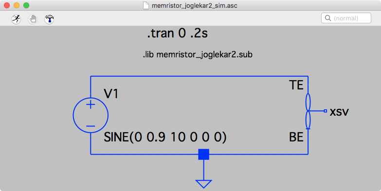
LTSpice Circuit Joglekar
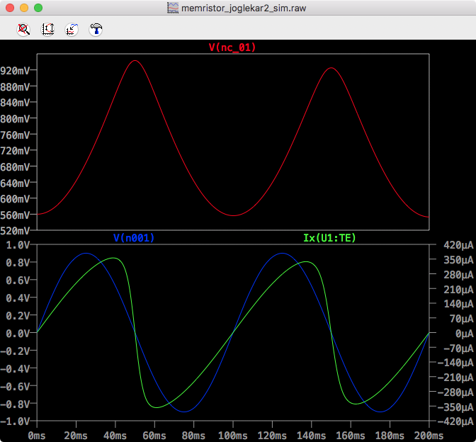
LTSpice Joglekar Time
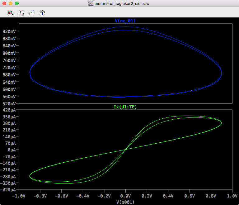
LTSpice Joglekar IV
Biolek Window
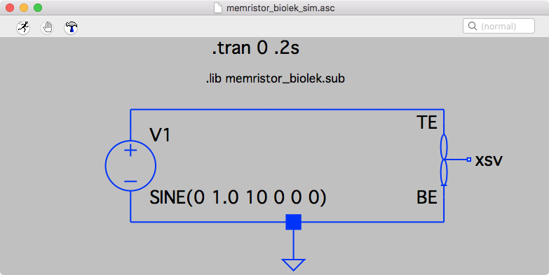
LTSpice Circuit Biolek
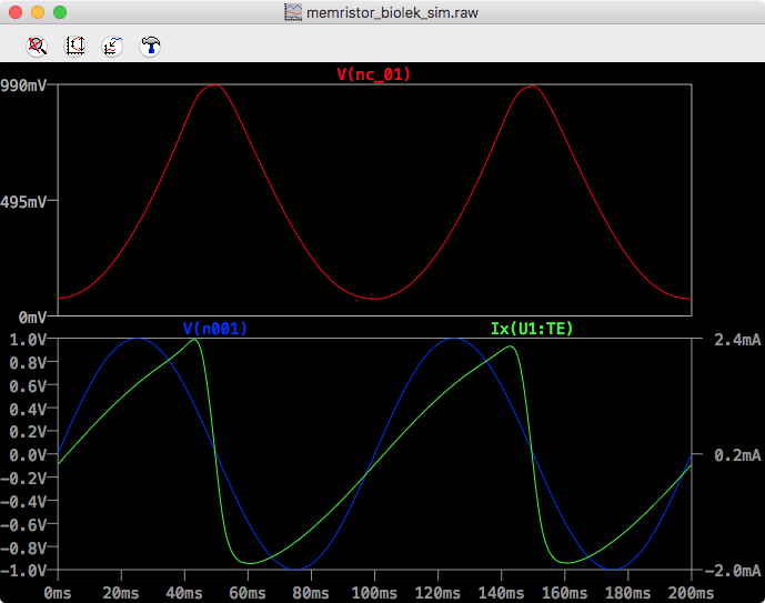
LTSpice Biolek Time
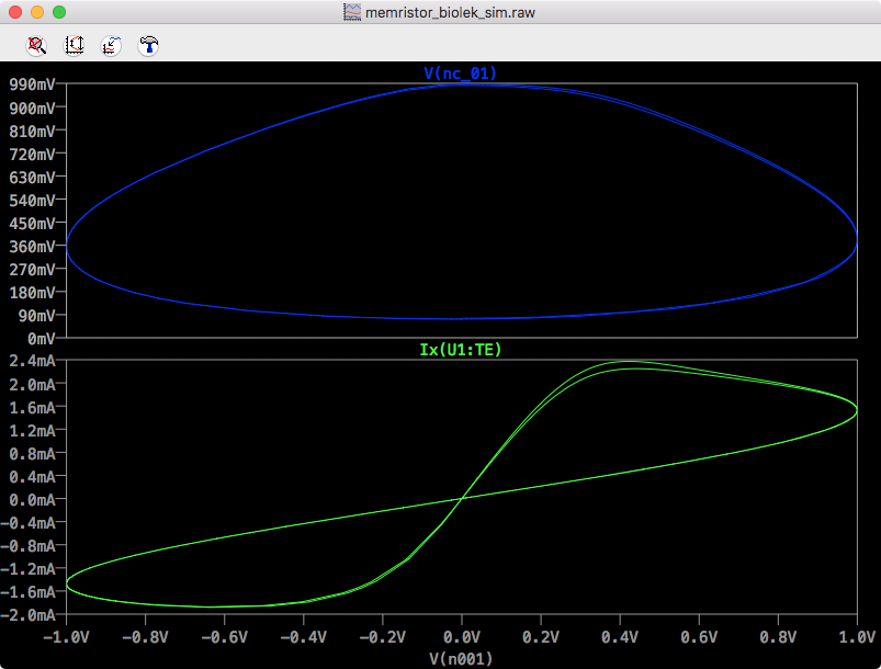
LTSpice Biolek IV
Yakopcic
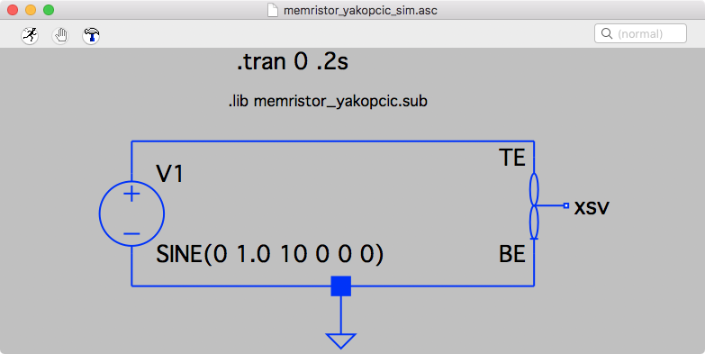
LTSpice Circuit Yakopcic
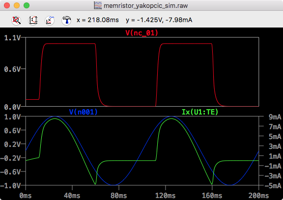
LTSpice Yakopcic Time
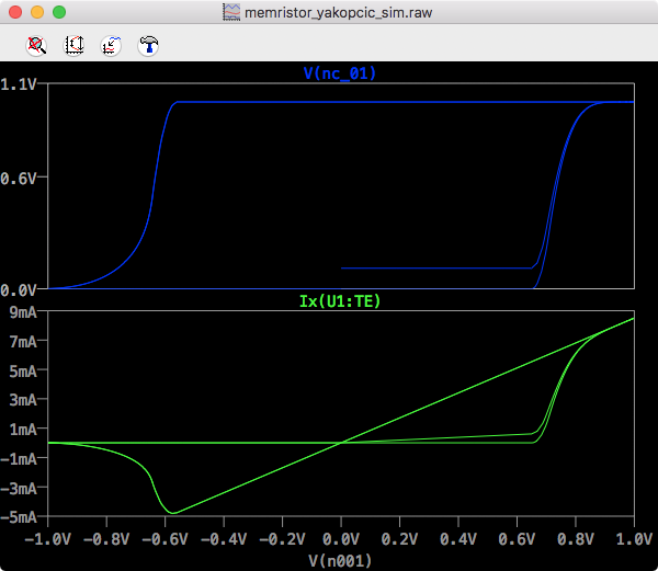
LTSpice Yakopcic IV
University of Michigan

LTSpice Circuit UMich
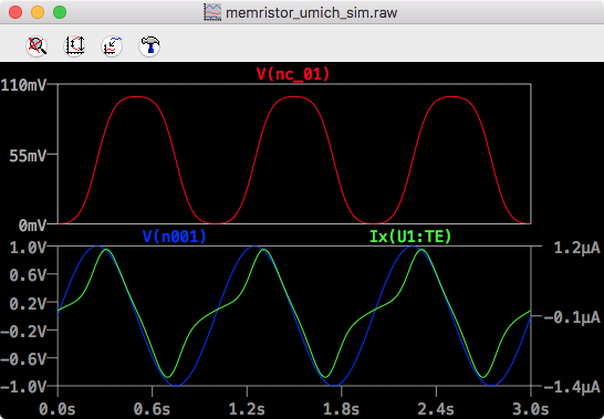
LTSpice UMich Time
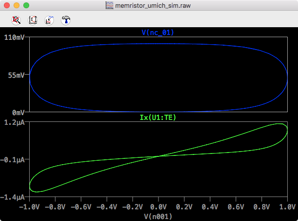
LTSpice UMich IV
Knowm
Because this model does not appear in Yakopcic’s book chapter referenced above, I will include a quick review of the mode and the LTSpice subcircuit here.
The Mean Metastable Switch Memristor Model
The mean metastable switch memristor model was previously described here, but I will summarize it again here for completeness. The model describes a memristor as a collection of metastable switches where each switch can be in either one or the other state. At any given time, the probability of switches switching state as a function of applied voltage is calculated.
The change in the number of switches, scaled between 0 and 1, 

If the probabilities 

}}}}")
}}}}\right)\right)")
The number of switches switching state is thus:
")
")
. Therefore plugging everything in, also setting 
 - P_{ON \rightarrow OFF} \cdot X")
}}}} \cdot (1-X) - \frac{dt}{\tau} \left(1 - \left(\frac{1}{{1 + {e^{ -\beta \left( {V + {V_{OFF}}} \right)}}}}\right)\right) \cdot X")
![dX/dt = 1/\tau \left[ \frac{1}{{1 + {e^{ -\beta \left( {V - {V_{ON}}} \right)}}}} \cdot (1-X) - \left(1 - \left(\frac{1}{{1 + {e^{ -\beta \left( {V + {V_{OFF}}} \right)}}}}\right)\right) \cdot X \right]](https://s0.wp.com/latex.php?latex=++dX%2Fdt+%3D+1%2F%5Ctau+%5Cleft%5B+%5Cfrac%7B1%7D%7B%7B1+%2B+%7Be%5E%7B+-%5Cbeta+%5Cleft%28+%7BV+-+%7BV_%7BON%7D%7D%7D+%5Cright%29%7D%7D%7D%7D+%5Ccdot+%281-X%29+-+%5Cleft%281+-+%5Cleft%28%5Cfrac%7B1%7D%7B%7B1+%2B+%7Be%5E%7B+-%5Cbeta+%5Cleft%28+%7BV+%2B+%7BV_%7BOFF%7D%7D%7D+%5Cright%29%7D%7D%7D%7D%5Cright%29%5Cright%29+%5Ccdot+X+%5Cright%5D+&bg=ffffff&fg=000000&s=0 "dX/dt = 1/\tau \left[ \frac{1}{{1 + {e^{ -\beta \left( {V - {V_{ON}}} \right)}}}} \cdot (1-X) - \left(1 - \left(\frac{1}{{1 + {e^{ -\beta \left( {V + {V_{OFF}}} \right)}}}}\right)\right) \cdot X \right]")
The final step to complete the MMSS model description is to define the current as a function of X. We can break that definition down into two steps, first the conductance, followed by the current. The conductance as a function of X is

Note that this describes a summation of conductances. Relating this to the real-world it tells us that our model is in fact 2 parallel resistors whose resistance values are coupled to each other via X.
For completeness, given a memristance value, for example 
}{ R_{init} (R_{ON} - R_{OFF})}")
Finally, by Ohm’s Law the current is

Subcircuit
|
1 2 3 4 5 6 7 8 9 10 11 12 13 14 15 16 17 18 19 20 21 22 23 24 25 26 27 28 29 30 31 32 33 34 35 36 37 38 39 40 41 |
* Knowm Mean Metastable Switch Memristor SPICE Model * Copyright Tim Molter Knowm Inc. 2017 * Connections: * TE: Top electrode * BE: Bottom electrode * XSV: External connection to plot state variable * that is not used otherwise .SUBCKT MEM_KNOWM TE BE XSV * Ron: Minimum device resistance * Roff: Maximum device resistance * Von: Threshold voltage to turn device on * Voff: Threshold voltage to turn device off * TAU: Time constant * T: Temperature .params Ron=500 Roff=1500 Voff=0.27 Von=0.27 TAU=0.0001 T=298.5 x0=0 * Function G(V(t)) - Describes the device threshold .func G(V) = V/Ron+(1-V)/Roff * Function F(V(t),x(t)) - Describes the SV motion .func F(V1,V2) = (1/TAU)*(( 1/(1+exp(-1/(T*boltz/echarge)*(V1-Von))) )*(1-V2)-( 1-(1/(1+exp(-1/(T*boltz/echarge)*(V1+Voff)))) )*V2 * Memristor I-V Relationship .func IVRel(V1,V2) = V1*G(V2) * Circuit to determine state variable * dx/dt = F(V(t),x(t))*G(V(t)) Cx XSV 0 {1} .ic V(XSV) = x0 Gx 0 XSV value={F(V(TE,BE),V(XSV,0))} * Current source for memristor IV response Gmem TE BE value={IVRel(V(TE,BE),V(XSV,0))} .ENDS MEM_KNOWM |
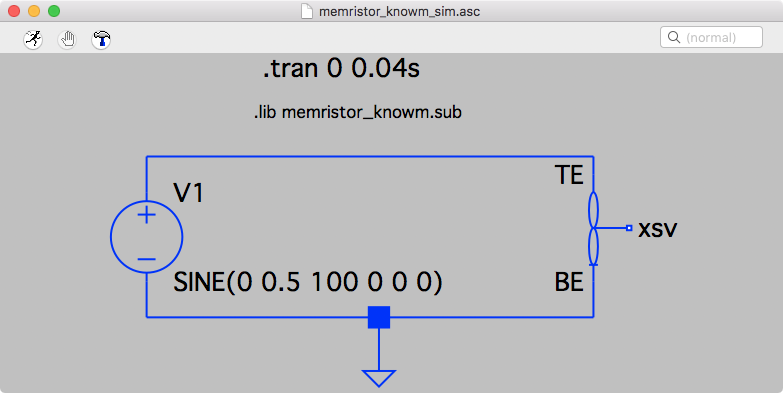
LTSpice Circuit Knowm
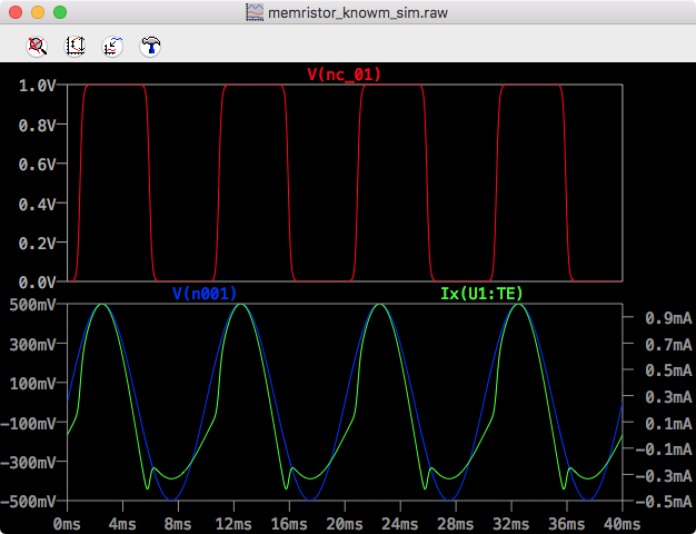
LTSpice Knowm Time
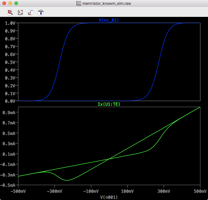
LTSpice Knowm IV
Conclusion
In this post I presented my simulation results taken more or less directly from Chris Yakopcic’s book chapter in the book titled Advances in Neuromorphic Memristor Science and Applications. I didn’t run all of the examples in the chapter, but doing so shouldn’t be hard at all. One of the motivations for running these simulations was to understand the basic mechanics of memristor modeling in LTSpice so that I could implement Knowm’s mean metastable switch memristor model, which I presented as the last simulation.
Further Resources
- Knowm Memristors
- The Generalized Metastable Switch Memristor Model
- The Problem is Not HP’s Memristor–It’s How They Want To Use It
- The Joglekar Resistance Switch Memristor Model in LTSpice
- Build Xyce from Source for ADMS Verilog-A Model Integration
- The Pershin Voltage Threshold Memristor Model in NGSpice
- memristor-models-4-all Project on Github
- Well-posed Memristor Modeling with Xyce and Verilog-A
- Native Memristor Device Development in Xyce
- The Mean Metastable Switch Memristor Model in Xyce


8 Comments
Shivam Acharya
Hi,
I am an undergrad university student and currently learning about memristors and crossbar arrays. I am trying to use one of the above-mentioned memristors models in LTSpice in a cross bar. I am not able to understand how to change the Ron and Roff values when used in a crossbar array. Do help me understand that. That would be very helpful.
Thanks.
Alex Nugent
Shivam,
Memristors typically need current limiting to prevent burn-out. This means that setting Ron value is determined mostly by current-limiting within your circuit and drivers. Knowm memristors will go all the way to 100Ω or even lower if you keep a positive voltage over the threshold. However, these high currents will damage the device. Roff is memristor and history dependent. For example, the Roff value of a Knowm W memristor is ~1MΩ except if it has driven with high current (~1mA). In this case Roff will reduce to anywhere from 50kΩ to 200kΩ.
Thanasin Bunnam
Hi, I simulated the original circuit from https://github.com/knowm/memristor-models-4-all/tree/master/Knowm/LTSpice in LTSpice. I set the sine wave amplitude as 0V because I want to see the state variable V(nc_01) stops changing. However, it still changes. Please suggest why the state variable changes while the input voltage is below the threshold? Thank you in advance.
Alex Nugent
Which memristor model are you using? If you are using the MSS model, the transition probabilities (Pa, Pb) that move the meta-stable switches are not discontinuous but given by continuous functions which are also a function of temperature. The switches will flip with small probability even if under threshold until an equilibrium is reached. Note that the MSS model is not an official model of the M-SDC devices. The MSS model was created before the M-SDC memristors were invented. That said, all memristors will decay to a degree outside the influence of external voltage bias so its important to capture that effect. https://knowm.org/the-generalized-metastable-switch-memristor-model/
Thanasin Bunnam
Yes, I’m studying the MSS model to see how it fits to the SDC memristor. Your reply was clear, thank you very much.
syed abdul rahim
1) sir, actually we need .sub file and .asy file to get symbol in ltspice.
but u have posted only .sub file.
is there any way to design with only .sub ckt file?
2) another question is how to select doped and undoped value. if it changes the value then what parameters will change in memristor.
3) and what is the main diff between linear and nonlinear memristor?
4) in ltspice how to create x and f(x) curve and parameters.
5) how to create a new model of memristor?
can u please reply me…..
Yash
@syed, please find some help from this
https://knowm.org/the-joglekar-resistance-switch-memristor-model-in-ltspice/
Prachi Upadhyay
I have been working with the Joglekar model for quite sometime, and I used both your netlist models, one without the XSV port and one with the XSV port. On using the model with XSV port, there is a gradual decrease in the current amplitude, it can be well seen when we incorporate more number of cycles. Can you explain the reason for it?