[popupwfancybox id=”6″]
In a previous post titled Well-posed Memristor Modeling with Xyce and Verilog-A, we showed how to create Verilog memristor models for simulation in Xyce. In this post, we take memristor modeling in Xyce one step further and show how to create a device model from scratch written in C, just like all the existing native devices found in Xyce. At the time of this writing, there doesn’t exist a complete official guide for writing native device models in Xyce. To figure all this out I pieced together various documents, got great help from the Xyce team on the Xyce Users Forum, and learned from long sessions of trial and error. I hope this “Unofficial Xyce Native Device Guide” is helpful to someone else attempting to create a native model in Xyce and helps avoid some of the pitfalls that I ran across.
In line with previous memristor modeling posts, I will stick with implementing the Joglekar memristor model for sake of demonstration.
Specialized Xyce Documentation
There is some unofficial documentation that can be generated from the Xyce source code, which can be used to gain insight into how the Xyce engine works and how devices are hooked into the simulator. Reading the Xyce Mathematical Formulation documentation is also helpful. While both documents are useful, there are some holes in the explanations. It would be useful if the Xyce Mathematical Formulation document tied the theory to practice by referencing code in the core simulator and in one or more device implementations. The source code documentation could also be improved with better documentation that describes what’s specifically being done in the code, especially for different devices. The existing memristor model implementations lack useful comments almost completely.
You can generate the Doxygen documentation if you have Doxygen and graphviz installed on your system (it should be available in the same package management system you used to obtain your third party libraries for building Xyce). Simply cd to the “doc/doxygen” directory of Xyce 6.6, and type “doxygen Doxyfile”. The files mentioned in the “device intro” will be created.
Let’s assume we have a directory for installing Xyce called ~/workspaces/workspace_eda and that you installed the source code there in folder Xyce-6.6. Generate the docs like this:
|
1 2 3 4 5 |
brew install doxygen brew install graphviz cd ~/workspaces/workspace_eda/Xyce-6.6/doc/doxygen doxygen Doxyfile |
A folder titled html will be generated with a ton of files. Open up index.html in a browser. You’ll want to click on Circuit Device How To ... in the left side column and read through that to get started.
See What buildxyceplugin Produces
While it is not recommended to use an ADMS-generated device implementation to bootstrap your own device development, if you have been creating Verilog-A models and integrating them into Xyce, it may be worthwhile to see what C file was generated from your Verilog-A file.
To see the C output of ADMS, you can use the “-d” option of buildxyceplugin, which will simply prevent the script from deleting the intermediate files it produces.
|
1 2 |
buildxyceplugin -d -o hys*.va /usr/local/lib |
According to a request for help on the xyce-users forum:
You are probably best copying one of the existing MemristorTEAM model and replacing its guts. Those files will have enough of the basic boilerplate to serve as a template. The code generated by ADMS could also be used as a template, but may contain unnecessary and distracting complications. Make sure to change the level number in the registerDevice and registerModelType calls in the registerDevice function.
In other words, cloning an existing device implementation and tweaking it is the better approach as the Verilog-A/ADMS method creates too much code bloat.
Prerequisites
The following instructions assume you’ve built Xyce from source previously. If you haven’t read Build Xyce from Source for ADMS Verilog-A Model Integration yet, you should go ahead and do that before continuing on.
The TEAM Memristor Model in Xyce
As a first step, we make sure we can actually simulate the TEAM memristor model in Xyce. We take the example directly out of the Xyce Reference Guide on page 484.
|
1 2 3 4 5 6 7 8 9 10 11 12 13 14 15 16 17 18 19 |
* Voltage Sources V1 1 0 SIN(0V 1.2V 1Hz) * Memristors ymemristor mr1 1 0 mrm1 .model mrm1 memristor level=2 ron=50 roff=1000 + IVRELATION=0 koff=1.46e-18 kon=-4.68e-22 + alphaoff=10 alphaon=10 wc=1.0e-12 + ioff=115e-6 ion=-8.9e-6 xscaling=1.0e9 wt=4 * Analysis Command .TRAN 1ms 1s * Output .PRINT TRAN V(1) I(V1) .END |
The resulting plot looks like this.
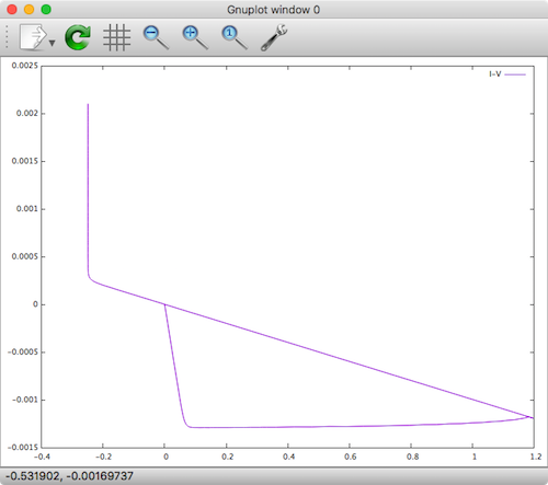
TEAM Memristor Xyce
It definitely looks strange, but at least it sort of looks like a hysteresis loop. I also tried some of the other window functions, but none of them worked. I either got straight line plots or the initial DC operation failed to converge. While I probably needed to play around with the other parameters more, I gave up.
The Yakopcic Memristor Model in Xyce
Next, we try the Yakopcic model from Xyce, again taking the example directly out of the Xyce Reference Guide on page 484.
|
1 2 3 4 5 6 7 8 9 10 11 12 13 14 15 16 17 18 |
* Voltage Sources V1 1 0 SIN(0V 1.2V 1Hz) * Memristors ymemristor mr1 1 0 mrm1 .MODEL mrm1 memristor level=3 a1=0.17 a2=0.17 b=0.05 vp=0.16 vn=0.15 + ap=4000 an=4000 xp=0.3 xn=0.5 alphap=1 alphan=5 eta=1 * Analysis Command .TRAN 1ms 1s * Output .PRINT TRAN V(1) I(V1) .END |
The resulting plot looks like this.
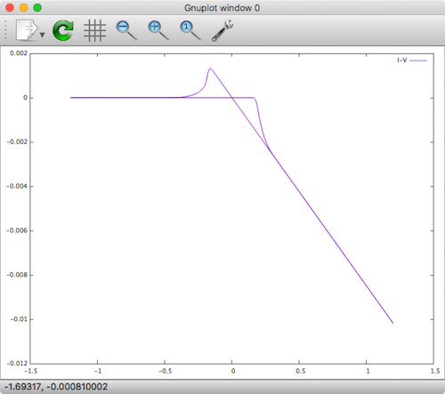
Yakopcic Memristor Xyce
That looks much more like a successful memristor device hysteresis loop. It does however look like the current direction is flipped. I decided to clone this device as a basis for building my new memristor device into Xyce.
The Cloned Yakopcic Memristor Model in Xyce
The next baby step is to clone the Yakopcic C and H files in the source tree, name them something different and update all the required source code. At this point, we’re not changing functionality, but just trying to setup the structure for a new model. I copied and pasted the files: N_DEV_MemristorYakopcic.C and N_DEV_MemristorYakopcic.h and renamed them N_DEV_MemristorJoglekar.C and N_DEV_MemristorJoglekar.h respectively. I then replaced all character strings in both files MemristorYakopcic with MemristorJoglekar.
In N_DEV_MemristorJoglekar.h, I updated the following struct, creating a new Y device type with name YJOGLEKAR.
|
1 2 3 4 5 6 7 |
struct Traits : public DeviceTraits<Model, Instance> { static const char *name() {return "MemristorJoglekar";} static const char *deviceTypeName() {return "YMEMRISTOR level 4";} ... }; |
In N_DEV_MemristorJoglekar.C, I updated the following method, defining a new device type called joglekar with a model level 1. I guess it would have also been possible to just create another memristor device type and give it a level=4, as 2 and 3 already exist for the TEAM and Yapokcic models respectively.
|
1 2 3 4 5 6 7 |
void registerDevice() { Config<Traits>::addConfiguration() .registerDevice("memristor", 4) .registerModelType("memristor", 4); } |
Updating Some More Files
In the following files, I needed to add references to the new model.
src/DeviceModelPKG/OpenModels/Makefile.amsrc/DeviceModelPKG/OpenModels/src/N_DEV_RegisterOpenDevices.Csrc/DeviceModelPKG/OpenModels/CMakeLists.txt
It’s pretty obvious what needs to be added to these files, so I won’t explain it here in detail.
Rebuild Xyce
There are 3 steps we need to take now to rebuild Xyce: 1) run “bootstrap” script at the top level directory to regenerate all the Makefile.in files in the source tree, 2) re-run configure in your build directory, and 3) build it.
Bootstrap
Let’s assume we have a directory where the Xyce source code exists called ~/workspaces/workspace_eda/Xyce-6.6.
|
1 2 3 |
cd ~/workspaces/workspace_eda/Xyce-6.6 ./bootstrap |
If you are following along on a Mac you may need to first install the following tools with Homebrew:
|
1 2 3 |
brew install autoconf brew install automake |
, otherwise you will probably get the following errors when running ./bootstrap:
|
1 2 3 4 5 6 7 8 9 10 11 12 13 14 15 16 17 18 19 20 |
5) autoheader ./bootstrap: line 4: autoheader: command not found 4) libtoolize glibtoolize: putting auxiliary files in AC_CONFIG_AUX_DIR, 'config'. glibtoolize: copying file 'config/ltmain.sh' glibtoolize: putting macros in AC_CONFIG_MACRO_DIRS, 'config'. glibtoolize: copying file 'config/libtool.m4' glibtoolize: copying file 'config/ltoptions.m4' glibtoolize: copying file 'config/ltsugar.m4' glibtoolize: copying file 'config/ltversion.m4' glibtoolize: copying file 'config/lt~obsolete.m4' 3) aclocal ./bootstrap: line 14: aclocal: command not found 2) automake ./bootstrap: line 16: automake: command not found 1) autoconf ./bootstrap: line 32: autoconf: command not found 0) autoheader, again ./bootstrap: line 35: autoheader: command not found |
After successfully running the ./bootstrap script, you should see that src/DeviceModelPKG/OpenModels/Makefile.in has been updated.
Configure
|
1 2 3 |
cd ~/workspaces/workspace_eda/Xyce-6.6/build/serial ./reconfigure |
Note: To see device debug outputs (useful later when debugging device implementation) add --enable-debug_device to the above config file.
Build
|
1 2 3 |
make -j4 sudo make install |
Quick Command Summary
|
1 2 3 4 5 6 7 8 |
cd ~/workspaces/workspace_eda/Xyce-6.6 ./bootstrap cd build/serial ./reconfigure sudo chown -R timmolter:staff ~/workspaces/workspace_eda/Xyce-6.6/build/serial/src/.libs make -j4 sudo make install |
Once the new device is hooked into Xyce, you need to compile the changes:
|
1 2 3 4 |
sudo chown -R timmolter:staff ~/workspaces/workspace_eda/Xyce-6.6/build/serial/src/.libs make -j4 sudo make install |
Running Simulation of New Device
At this point and before coding the new device behavior it’s worth making sure everything is still working. Since I just cloned the Yakopcic model and gave it it new name, it should be possible to get the previous results by just changing the device name from ymemristor to YJOGLEKAR.
Device Implementation
Before diving into making changes to the cloned device implementation, it’s worth figuring out exactly where changes need to be made, and which code blocks can more or less be ignored.
Model Params
Each device will have some model parameters that define it. The parameters need to be defined and also loaded from the simulation file. The params are defined in N_DEV_MemristorJoglekar.h in the Model class:
|
1 2 3 4 5 6 7 8 9 10 |
... // model parameters for Joglekar model double Roff_; double Ron_; double D_; double uv_; double p_; ... |
The model params are loaded in N_DEV_MemristorJoglekar.C in the Traits::loadModelParameters method:
|
1 2 3 4 5 6 7 8 9 10 11 12 13 14 15 16 17 18 19 20 21 22 23 24 25 |
void Traits::loadModelParameters(ParametricData<MemristorJoglekar::Model> &p) { // Create parameter definitions for parameter member variables // NOTE: The first string arg needs to be ALL CAPS! p.addPar("ROFF", 16000.0, &MemristorJoglekar::Model::Roff_) .setUnit(U_OHM) .setDescription("Off resistance."); p.addPar("RON", 100.0, &MemristorJoglekar::Model::Ron_) .setUnit(U_OHM) .setDescription("On resistance"); p.addPar("D", 10.0e-9, &MemristorJoglekar::Model::D_) .setUnit(U_METER) .setDescription("Width of the thin film"); p.addPar("UV", 10.0e-15, &MemristorJoglekar::Model::uv_) .setUnit(U_NONE) .setDescription("Migration coefficient"); p.addPar("P", 1.0, &MemristorJoglekar::Model::p_) .setUnit(U_NONE) .setDescription("Parameter of the WINDOW-function for modeling nonlinear boundary conditions"); } |
Note that the first string argument needs to be ALL CAPS.
Instance Params
Each device can also have instance parameters. For a memristor this could be the initial state of the device. The params are defined in N_DEV_MemristorJoglekar.h in the Instance class:
|
1 2 3 4 5 |
... // User-specified parameters: double R_init_; ... |
The instance params are loaded in N_DEV_MemristorJoglekar.C in the Traits::loadInstanceParameters method:
|
1 2 3 4 5 6 7 8 |
void Traits::loadInstanceParameters(ParametricData<MemristorJoglekar::Instance> &p) { p.addPar("R_init", 0.0, &MemristorJoglekar::Instance::R_init_) .setUnit(U_OHM) .setDescription("Initial value for resistance"); } |
Device Behavior
There are lots of methods in the device class that need to be implemented, however most of them can be ignored as they are simply boiler plate code necessary to integrate the device into the main Xyce simulation engine.
Xyce solves the Differential-Algebraic equation (DAE) F(X)+dQ(X)/dt = 0, and there are methods that you will need to implement to load values into the F and dQ matrices and vectors according to the Xyce rules and conventions.
Regarding the DAE functionality there are 6 methods that look important but can also be ignored. These can be ignored and left blank in the case of the original cloned Yakopcic memristor model because the model implements this functionality in three different but functionally identical methods in the Master class.
|
1 2 3 4 5 6 7 8 9 10 11 12 13 14 15 16 17 18 19 20 21 22 23 24 25 26 27 28 29 30 31 32 |
// The following 6 methods can return true because the methods in the Master implementation cover this functionality. bool Instance::loadDAEQVector() { return true; } bool Instance::loadDAEFVector() { return true; } bool Instance::loadDAEdQdx() { return true; } bool Instance::loadDAEdFdx() { return true; } bool Instance::updatePrimaryState() { return true; } bool Instance::updateIntermediateVars() { return true; } |
From a help request by me on the Xyce Users Forum, there’s a bit more explanation about the DAE mechanism:
Xyce solves the Differential-Algebraic equation (DAE): F(X)+dQ(X)/dt = 0
The equation is basically Kirchoff’s current law. F(X) are those currents that can be computed directly, and dQ/dt are the currents from time-varying charges. Devices are responsible for loading F and Q each time they are called, as well as the Jacobian matrix for each term, dF/dX and dQ/dX. The Xyce time integrator takes care of differentiating Q and dQ/dX when trying to solve the DAE.
In Verilog terms, F will get any contributions that are strictly static:
I(a,b) <+ function(V(a,b), V(b,c), V(c,d)…);Q will be formed from contributions with dynamic terms:
I(a,b) <+ ddt(charge);
I(b,c) <+ L*ddt(V(b,c));What is actually loaded into Q will be the RHS with the “ddt” removed. In the first case, Q(li_a) will get “charge” and Q(li_b) will get “-charge”. In the second, Q(li_b) will get LV(b,c) and Q(li_c) willg et -L(V(b,c)).
With Xyce/ADMS, that’s all you have to write, and ADMS generates the appropriate dF/dX and dQ/dX terms as well. If you’re writing in C++ directly, you have to code all that stuff yourself. You also have to be sure to set up the sparse matrix pattern (“jacobian stamp”) that defines where these quantities will be placed in the full system Jacobian.
Ignoring the above-mentioned 6 methods, the remaining three methods which must be implemented are:
- Master::updateState
- Master::loadDAEVectors
- Master::loadDAEMatrices
Following are the three methods as I implemented them. Note that if you want to print out values to the console during simulation, you can use the Xyce::dout() << " x = " << x << std::endl; mechanism.
|
1 2 3 4 5 6 7 8 9 10 11 12 13 14 15 16 17 18 19 20 21 22 23 24 25 26 27 28 29 30 31 32 33 34 35 36 37 38 39 40 41 42 43 44 45 46 47 48 49 50 51 52 53 54 55 56 |
bool Master::updateState(double * solVec, double * staVec, double * stoVec) { for (InstanceVector::const_iterator it = getInstanceBegin(); it != getInstanceEnd(); ++it) { Instance & ri = *(*it); double v_pos = solVec[ri.li_Pos]; double v_neg = solVec[ri.li_Neg]; double x = solVec[ri.li_x]; // handle boundary conditions - ugly hack if(x <= 0){ x = 0.001; }else if(x >= 1){ x = 1 - 0.001; } if (DEBUG_DEVICE){ Xyce::dout() << " x = " << x << std::endl; } { Sacado::Fad::SFad<double,3> varV1( 3, 0, v_pos ); Sacado::Fad::SFad<double,3> varV2( 3, 1, v_neg ); Sacado::Fad::SFad<double,3> varX( 3, 2, x ); Sacado::Fad::SFad<double,3> resultFad; resultFad = I_V( varV1, varV2, varX, ri.model_.Ron_, ri.model_.Roff_); ri.i0 = resultFad.val(); // current ri.G = resultFad.dx(0); // di/dv = conductance ri.dIdx = resultFad.dx(2); // di/dx } { // evaluate the state variable equation Sacado::Fad::SFad<double,3> varV1( 3, 0, v_pos ); Sacado::Fad::SFad<double,3> varV2( 3, 1, v_neg ); Sacado::Fad::SFad<double,3> varX( 3, 2, x ); Sacado::Fad::SFad<double,3> resultFad; resultFad = X_var_F( varV1, varV2, varX, ri.model_.uv_, ri.model_.Ron_, ri.model_.Roff_, ri.model_.D_, ri.model_.p_ ); ri.xVarFContribution = resultFad.val(); ri.dxFEqdVpos = resultFad.dx(0); ri.dxFEqdVneg = resultFad.dx(1); ri.dxFEqdx = resultFad.dx(2); } } return true; } |
|
1 2 3 4 5 6 7 8 9 10 11 12 13 14 15 16 17 18 19 20 21 22 23 24 25 26 27 28 29 |
bool Master::loadDAEVectors (double * solVec, double * fVec, double *qVec, double * bVec, double * leadF, double * leadQ, double * junctionV) { for (InstanceVector::const_iterator it = getInstanceBegin(); it != getInstanceEnd(); ++it) { Instance & ri = *(*it); fVec[ri.li_Pos] += ri.i0; fVec[ri.li_Neg] += -ri.i0; fVec[ri.li_x] += ri.xVarFContribution; qVec[ri.li_x] -= solVec[ri.li_x]; if( getSolverState().dcopFlag ) { qVec[ri.li_x] -= ((ri.model_.Roff_ - ri.R_init_) / (ri.model_.Roff_ - ri.model_.Ron_)) ; } if( ri.G != 0 ) { double * storeVec = ri.extData.nextStoVectorRawPtr; storeVec[ri.li_store_R] = 1.0/ri.G; } if( ri.loadLeadCurrent ) { leadF[ri.li_branch_data] = ri.i0; junctionV[ri.li_branch_data] = solVec[ri.li_Pos] - solVec[ri.li_Neg]; } } return true; } |
|
1 2 3 4 5 6 7 8 9 10 11 12 13 14 15 16 17 18 19 20 21 22 23 24 25 26 27 28 29 30 31 32 33 |
bool Master::loadDAEMatrices(Linear::Matrix & dFdx, Linear::Matrix & dQdx) { for (InstanceVector::const_iterator it = getInstanceBegin(); it != getInstanceEnd(); ++it) { Instance & ri = *(*it); #ifndef Xyce_NONPOINTER_MATRIX_LOAD *(ri.f_PosEquPosNodePtr) += ri.G; *(ri.f_PosEquNegNodePtr) -= ri.G; *(ri.f_PosEquXNodePtr) += ri.dIdx; *(ri.f_NegEquPosNodePtr) -= ri.G; *(ri.f_NegEquNegNodePtr) += ri.G; *(ri.f_NegEquXNodePtr ) += ri.dIdx; *(ri.f_XEquPosNodePtr ) += ri.dxFEqdVpos; *(ri.f_XEquNegNodePtr ) += ri.dxFEqdVneg; *(ri.f_XEquXNodePtr ) += ri.dxFEqdx; *(ri.q_XEquXNodePtr ) = -1.0; #else dFdx[ri.li_Pos][ri.APosEquPosNodeOffset] += ri.G; dFdx[ri.li_Pos][ri.APosEquNegNodeOffset] -= ri.G; dFdx[ri.li_Pos][ri.APosEquXNodeOffset] += ri.dIdx; dFdx[ri.li_Neg][ri.ANegEquPosNodeOffset] -= ri.G; dFdx[ri.li_Neg][ri.ANegEquNegNodeOffset] += ri.G; dFdx[ri.li_Neg][ri.ANegEquXNodeOffset] += ri.dIdx; dFdx[ri.li_x][ri.XEquVPosOffset] += ri.dxFEqdVpos; dFdx[ri.li_x][ri.XEquVNegOffset] += ri.dxFEqdVneg; dFdx[ri.li_x][ri.XEquXOffset] += ri.dxFEqdx; dQdx[ri.li_x][ri.XEquXOffset] = -1.0; #endif } return true; } |
Sacado Templates
Note that in Master::updateState there are two methods called: I_V and X_var_F. These use the Sacado template mechanism, which comes with the Trilinos package that Xyce heavily relies upon to accelerate their simulation engine. Information on how exactly these templates function is hard to come by, but I did find a couple of resources:
- Generative Programming for Automatic Differentiation – It works!
- Sacado: Automatic Differentiation Tools for C++ Codes
In N_DEV_MemristorJoglekar.C this is what I_V and X_var_F turned out to be.
I_V simply defines current as a function of voltage and the X variable.
|
1 2 3 4 5 6 7 8 9 10 11 12 13 14 15 16 17 18 19 20 21 22 23 24 25 26 27 28 29 30 31 32 |
template <typename ScalarT> ScalarT JogelkarWindowFunction( const ScalarT & X, double P ) { ScalarT fval = 1.0 - pow( (2.0*X - 1.0), (2*P) ); return fval; } // linear current voltage model, Reff template <typename ScalarT> ScalarT Reff( const ScalarT & X, double RON, double ROFF ) { return RON * X + ROFF * (1 - X); } template <typename ScalarT> ScalarT X_var_F( const ScalarT & V1, const ScalarT & V2, const ScalarT & X, double UV, double RON, double ROFF, double D, double P) { ScalarT Rval = Reff( X, RON, ROFF ); ScalarT Windowval = JogelkarWindowFunction(X, P ); return UV*RON/D/D/Rval*(V1-V2)*Windowval; } template <typename ScalarT> ScalarT I_V( const ScalarT & V1, const ScalarT & V2, const ScalarT & X, double RON, double ROFF ){ ScalarT Rval= Reff( X, RON, ROFF ); return (V1-V2)/Rval; } |
This equation was conveniently defined for us in Biolek’s paper on the model in equation 4. As a side note, for the Yakopcic model the relationship is defined in equation 7 in A Memristor Device Model.
Explanation of Differential-Algebraic equation (DAE) for Memristor Models
Admittedly, I don’t understand 100% how the Xyce team implemented the memristor model via these three DAE methods. I’m still trying to understand how it works, specifically the WHY of loading certain values into F, Q, fVec and qVec. I understand how the values that get put into F, Q, fVec and qVec are generated using the Sacado templates. I understand WHY the F matrix (3×3) elements (0,0), (0,1), (1,0) and (1,1) are set to G, -G, G, and -G respectively (just like how a resistor is implemented).
But here are my open questions when boiled down to the final details.
Given the Jacobian matrices shown here, implied from Master::loadDAEVectors and Master::loadDAEMatrices:
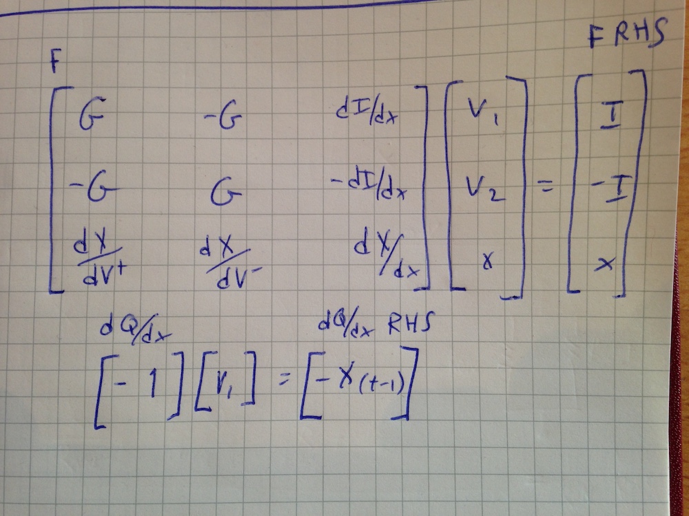
Xyce DAE
- Why is F(2,2) set to dX/dx and fVec(2) set to x?
- Why is Q(0,0) set to -1 and qVec(0,0) to -x[t-1]?
- Why are F(0,2), F(1,2), F(2,0), F(2,1) and fVec(0), fVec(1) set to values that seem to cancel out to zero? (My guess here is to keep the matrices dense.)
There seems to be an internal node defined x that is used to model the hysteresis behavior of a memristor, even though there is no “charge” being physically modeled. My best guess is that it’s modelling the memristor in a way similar to the way most SPICE models are implemented – as a voltage controlled voltage source regulated by an integrated change on a 1 F capacitor.
Simulation Results
After implementing the new Joglekar model, recompiling Xyce, creating a simulation file shown here:
|
1 2 3 4 5 6 7 8 9 10 11 12 13 14 15 |
* Voltage Sources V1 1 0 SIN(0V 1.2V 1Hz) * Memristors YMEMRISTOR mr1 1 0 mrm1 R_init=11000 .MODEL mrm1 memristor (level=4 Roff=16000 Ron=100 D=10e-9 uv=10e-15 p=2.0) * Analysis Command .TRAN 10ns 1s * Output .PRINT TRAN V(1) I(V1) N(YMEMRISTOR!mr1:R) .END |
, and simulating, the following hysteresis plot emerges.
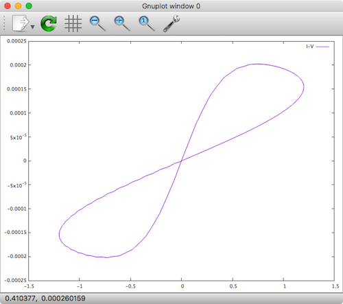
Xyce Native Joglekar Memristor
We see that the result is roughly the same as previously obtained when implementing the model in Verilog-A!
Conclusion
In this post I demonstrated how to implement the Joglekar memristor model natively in C code for the Xyce circuit simulator by first cloning an existing Yakopcic device model followed by implementing the Joglekar’s dX/dt behavior. Full source code for the model can be found at the memristor-models-4-all Project on Github.
Further Resources
- Knowm Memristors
- The Generalized Metastable Switch Memristor Model
- The Problem is Not HP’s Memristor–It’s How They Want To Use It
- The Joglekar Resistance Switch Memristor Model in LTSpice
- Build Xyce from Source for ADMS Verilog-A Model Integration
- The Pershin Voltage Threshold Memristor Model in NGSpice
- memristor-models-4-all Project on Github
- Well-posed Memristor Modeling with Xyce and Verilog-A


Leave a Comment