[popupwfancybox id=”6″]
In the post titled Simulating the Knowm M-MSS Memristor Model Pulse Response with Qucs-S and Xyce, I presented the dynamic behavior of the M-MSS model’s response to a square wave pulse with various pulse configurations while introducing some more advanced features of Qucs-S and Xyce integration. In this post I will discuss extensions to Qucs-S that have been added to support the Knowm JSpice SPICE-inspired simulator to run transient simulations of a memristor using the M-MSS (Mean Meta-Stable Switch Memristor Model). I will be comparing the simulation results of the M-MSS model’s response to a rectangular square wave pulse using while varying the pulse pulse width and duty cycle. The I will adding an Octave script to perform post analysis of the simulated data to extract resistance and conductance values and plot these values vs. the incremental pulse values to evaluate the incremental pulse response of the model.
An example Qucs-S project has been created to perform various experiments that we will later set up on actual memristor devices using the Knowm Memristor Discovery board and associated extender modules. The example Qucs-S/Xyce/JSpice compatible project knowm_mr_pulse_j experiment will be covered in this tutorial.
Prerequisites
Update to the latest release candidate rc5 of the Knowm OSS EDA Stack. It is available for macOS 10.12 Sierra and Ubuntu 16.04 LTS (Xenial Xerus). This post covers installation and use on macOS and support for Xyce (Serial) simulations only. JSpice is being delivered as an executable Java Archive .jar file. You will need to have Java installed on your computer before you can use the JSpice simulator. The provided versions of Qucs-S (0.0.19S) and Xyce 6.7 include libraries for amd64 architectures. Support for other architectures and operating systems are under development and will be released when available.
Please follow the detailed tutorial Comparing Simulation Results for the Knowm M-MSS Model in Xyce and JSpice Using Qucs-S to download the latest version of the Qucs-S, Xyce and JSpice binaries and get them configured properly. Running the example project circuits there will verify that everything is working properly.
Additional Software Installation
The following assumes you have downloaded the pre-built bundles for the Qucs-S, Xyce and JSpice.
Install GNU Octave – Scientific Programming Language
Octave provides powerful mathematics-oriented syntax with built-in plotting and visualization tools.
The Octave syntax is largely compatible with Matlab. The Octave interpreter can be run in GUI mode, as a console, or invoked as part of a shell script. It is accessed in Qucs by selecting View->Octave Window.
NOTE: Octave is not currently provided with the Knowm Opensource EDA Stack MacOS release so you will need to install it from the Octave site. We have tested with an older stable Octave version 4.0.3 for use with Qucs-S so it is recommended that you install this version for now. We will soon be updating to version 4.2.1 in the future which is available for MacOS from Homebrew and aptitude from Ubuntu Linux.
MacOS 10.12 Sierra Install
- To download the MacOS installer package from Source Forge go to the Octave 4.0.3 project wiki https://wiki.octave.org/Octave_for_macOS_X
-
On the Octave wiki site, under
Installing a Mac OS X Bundleclick on the linkdownload Octave 4.0.3 with graphical user interface (OS X 10.9+) -
Double-click on the downloaded
.dmgpackage and follow the steps in the Octave 4.0.3 installer to complete the installation of Octave. -
Verify Octave is found in the
/Applications/Octave.appfolder. -
You can test the install from the terminal console by typing:
|
1 2 |
% /Applications/Octave.app/Contents/Resources/usr/bin/octave --version |
Debian Linux Install – Ubuntu LTS (Xenial Xerus)
-
To install Octave 4.0.0 using
aptitudeyou will need to open a terminal window. -
Type the following command at the shell prompt:
|
1 2 |
$ sudo apt install octave |
-
Answer
Yto the prompt to begin the Octave installation. -
Verify Octave is installed correctly by typing at shell prompt:
|
1 2 |
$ which octave |
- You should get the response
|
1 2 |
$ /usr/bin/octave |
- You can test the install from the terminal console by typing:
|
1 2 |
$ /usr/bin/octave --version |
Launch Qucs-S
-
Click on the Qucs app icon on the Launcher Bar.
NOTE: the first time Qucs is started is will inform you that no default simulator has been selected.
-
Click
Okand then selectXyce (serial)as the default if prompted.
Qucs-S Application Settings
-
Select
File->Application Settings...from the menu. -
Click the
Locationstab.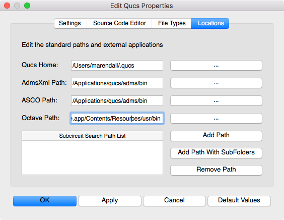
NOTE: The
Qucs Homewill be a folder named.qucsin your user$HOME/directory. This is where all projects will be stored for your installation. Each project will be stored in a separate sub-directory with the_prjsuffix appended to the name you specify. Other directories such as thespice4qucsdirectory will also be created which will store the data and netlist information for your Xyce and JSpice simulations.
Save the Application Settings
-
Click
Applyto save the settings. -
Click
OKto exit the settings dialog.
Open the KnowmMemristor_J_prj Examples Project File
-
Select the
Projectstab on the left of the Main Dock. -
Double click the
KnowmMemristor_J_prjto automatically open theContenttab.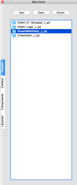
Select the Schematic diagram
-
Double click on the
knowm_mr_pulse_j.schfrom theSchematicslist in the Main Dock.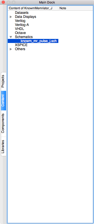
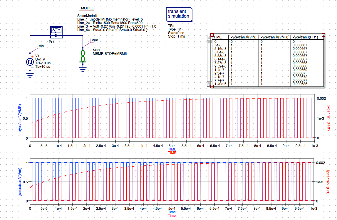
NOTE: We will be referring to the multiple components of this schematic in the following sections to familiarize you with the basic settings required to perform the transient simulation using Xyce and JSpice. You may want to consult the Qucs-S documentation and Xyce Reference Manual or the JSpice documentation on the Knowm JSpice Github page for more information on available settings.
-
Notice the
MR Memristorhas been placed on the schematic and the MRM5 model has been assigned to the MR1 component instance.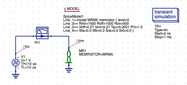
-
The .Model directive for the MRM5 model has been selected from a newly added
Knowm Memristor Technologylibrary found under theLibrariestab of the Main Dock.NOTE: This library will be the repository in Qucs-S for any new models developed and provided by Knowm.org and the Knowm Developer Community. The models and updates will also be featured on the
memristor-models-4-allGithub repository.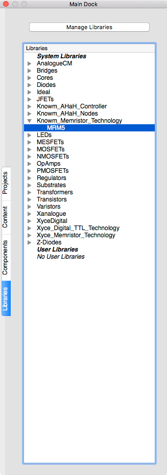
-
The Rectangle Voltage source has been selected from the
sourcesdrop-down list and the parameters set for a 10us Pulse Width and 20us Period.(TH + TL = Period).
NOTE: The voltage is set to
1 Vwhich will produce a pulse starting at0 Vfor theTLtime then it will transition to1 Vfor the specifiedTHtime.
Save the Schematic Diagram File
-
The filename
knowm_mr_pulse_j.schhas been used for this example schematic and will be used in future tutorials. -
Click the
Savebutton on the toolbar to save the schematic file.
Save Toolbar Button
Select Xyce (Serial) as the Default Simulator
-
Select
Simulation->Select default simulator.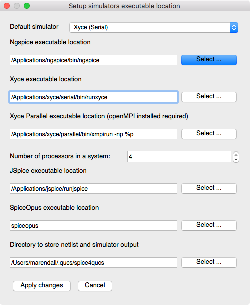
-
Verify the
Xyce (Serial) executable locationis set to/Applications/xyce/bin/runxyce. -
Select
Xyce (Serial)from theDefault simulatordrop-down-list. -
Click
Apply changes.NOTE: After changing the default simulator you will receive a warning to restart Qucs. This is not always necessary unless you want to make the selected simulator the new default for the project. For now just proceed and we will discuss this in more detail below in the
General Notes on Usage.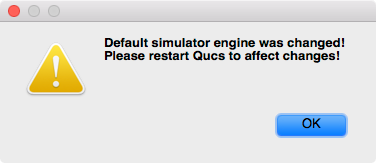
Run a Xyce Simulation
-
Press
Simulation->Simulateon the main menu or selectSimulatebutton on the toolbar.
Run Simulation Toolbar Button
-
Check simulation for
errorsorwarnings. See the status bar at the bottom of the Qucs windowlower right corner.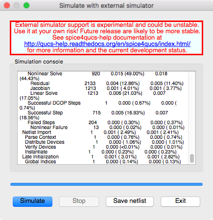
-
You can save the current netlist by clicking the
Save Netlistbutton on the simulation window.NOTE: The
F6key orShow Last Netlistfrom the Simulations menu currently only displays the last netlist for the latest
Qucsator simulation. If you save the netlist using the button on the simulation window then you can open the.cirfile underOtherslist in the project tree.
-
Click the
Exitbutton to close theSimulationwindow. -
You can view and messages written by the Xyce simulator by clicking the
F5key or selectingShow Last Messagesfrom the Simulations menu.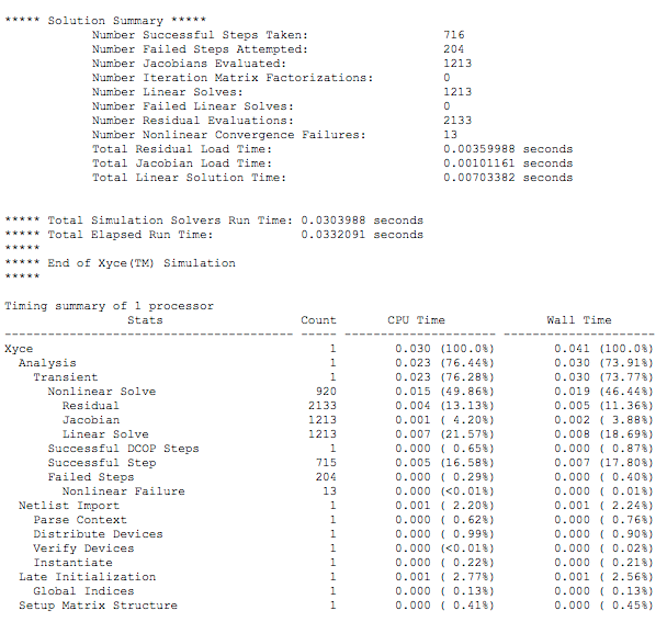
-
The
Qucsdata fileknowm_mr_pulse_j.dat.xyceproduced by the transient simulation will be automatically created in the$HOME/.qucs/KnowmMemristor_prj/directory.
Modifying the Experiment
Set Rectangle Pulse Voltage Source properties
-
Double click on the
Rectangular Voltagesymbol to open the parameters for the source. -
Leave the
1 Vamplitude for theUparameter unchanged for the pulse.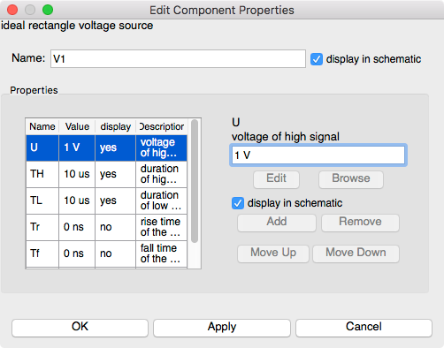
-
Select the
TLrow in the properties table.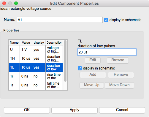
-
Change the
duration of low pulsesfrom10 usto20 us.
-
Verify the
display in schematiccheckbox is selected. -
Click
Applyto set theTLvalue. -
Click
OKto exit the properties dialog.
Save the Schematic Diagram File
-
Click the
Savebutton on the toolbar to save changes to theknowm_mr_pulse_j.schschematic file.Save Toolbar Button
Run the Modified Xyce Simulation
-
Press
Simulation->Simulateon the main menu or selectSimulatebutton on the toolbar.Run Simulation Toolbar Button
-
Check simulation for
errorsorwarnings. See the status bar at the bottom of the Qucs windowlower right corner. -
Click the
Exitbutton to close theSimulationwindow. -
The
Qucsdata fileknowm_mr_pulse_j.dat.xyceproduced by the transient simulation will be automatically created in the$HOME/.qucs/KnowmMemristor_J_prj/directory.
View the Tabular Results
-
Check the
Tabularresults.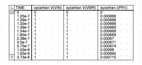
Cartesian Plot of Memristor I,V vs. Time Results
-
You should also observe the results in the specified Xyce I,V vs. Time plot defined in the schematic.
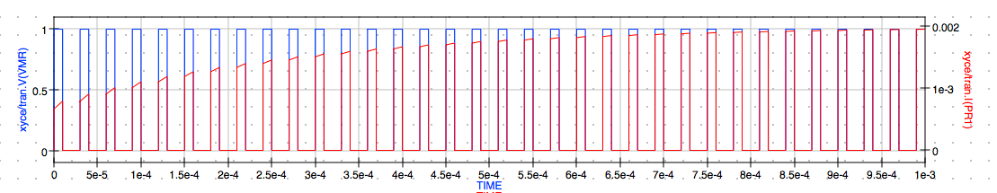
NOTE: The results contain
0 Vto1 Vwith the pulse width10 usat1 Vand20 uspulse width at0 Vwith a combined period of30 usand duty cycle33.3%.
Select JSpice as the Default Simulator
-
Verify the
JSpice executable locationis set to/Applications/jspice/runjspice. -
Select
Simulation->Select default simulator.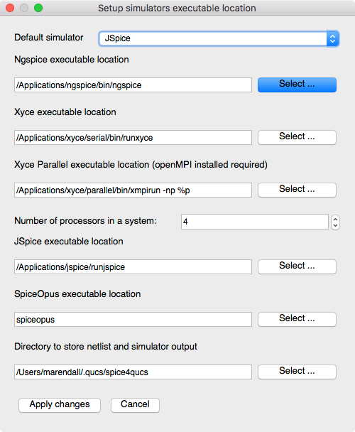
-
Select
JSpicefrom theDefault simulatordrop-down-list. -
Click
Apply Changes.NOTE: After changing the default simulator you will receive a warning to restart Qucs. This is not always necessary unless you want to make the selected simulator the new default for the project. For now just proceed and we will discuss this in more detail below in the
General Notes on Usage. -
Click
OK.
Run a JSpice Simulation
-
Select
Simulation->Simulateon the main menu or selectSimulatebutton on the toolbar.Run Simulation Toolbar Button
-
Check simulation for
errorsorwarnings. See the status bar at the bottom of the Qucs windowlower right corner.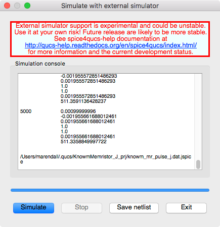
-
Again, if you want to save the current netlist, use the
Save netlistbutton on the external simulator window to open the file save dialog. Specify the name of the netlist to save, typically the schematic’s filename with the extension.cirinstead of.sch. The resulting file will be saved in the project folder and you can open the.cirfile under theOtherslist in the project tree.NOTE: The
F6key orShow Last Netlistfrom the Simulations menu currently only displays the last netlist for the lastest Qucsator simulation.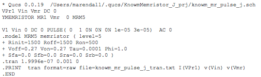
-
Click the
Exitbutton to close theSimulationwindow. -
You can view any messages written by the simulator by clicking the
F5key or selectingShow Last Messagesfrom the Simulations menu.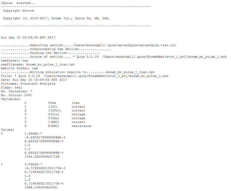
-
The
Qucsdata fileknowm_mr_pulse_j.dat.jspiceproduced by the transient simulation will be automatically created in the$HOME/.qucs/KnowmMemristor_J_prj/directory.
Cartesian Plot of Memristor I,V vs. Time Results
-
You should also observe the results in the specified JSpice I,V vs. Time plot defined in the schematic.
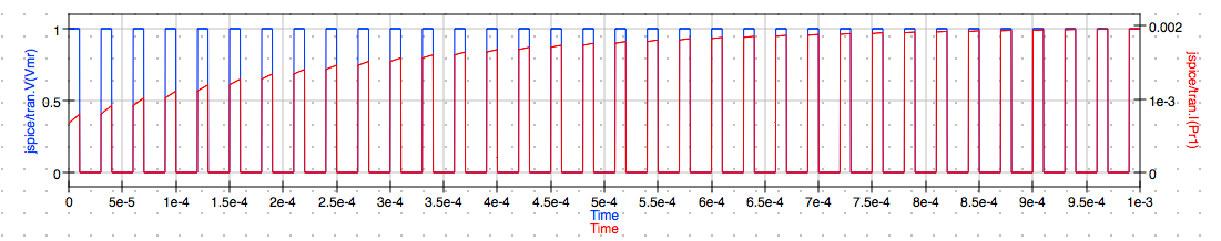
NOTE: The results again contain
0 Vto1 Vwith the pulse width10 usat1 Vand20 uspulse width at0 Vwith a combined period of30 usand duty cycle33.3%. These results closely agree with the Xyce simulation results above.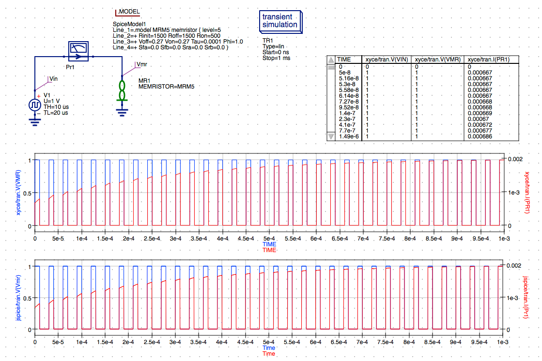
Calculate R(MR) and G(MR) vs. Pulse Number using Octave
For a detailed description of Octave script stuctures in Qucs-S and how to write and execute an Octave script to extract data from the simulation results read the post Using GNU Octave Scripts for Post-Analysis of Xyce Simulation Results within Qucs-S Graphical User Interface.
Set Document Settings
Only one of the two Qucs-S/Octave simulation data post-processing methods can be active at any one time. To select which check the correct boxes in the Edit File Properties window located under File->Document Settings. For example when box open data display after simulation is ticked and box run script after simulation is NOT ticked then the Manual method is selected. Reversing which box is ticked results in selection of the Automatic method of Octave post-simulation data processing.
- Right click on the schematic and select
Document Settings... -
Select
Simulationtab. -
Uncheck
open data display after simulationcheckbox in the dialog. -
Check the
run script after simulationcheckbox in the dialog.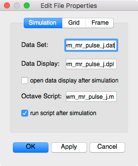
-
Click
Applyto save the changes. -
Click
OKto exit the properties dialog.
Save the Schematic Diagram File
-
Click the
Savebutton on the toolbar to save changes to theknowm_mr_pulse_j.schschematic file.Save Toolbar Button
Open Octave Window
The Octave interpreter can be run in Qucs-S GUI mode, as a console, or invoked as part of a shell script.
- Select
View->Octave Windowfrom the Main Menu.NOTE: This should open the Octave console window at the bottom of the screen and start the Octave command interpreter.
Run a Xyce Simulation
-
Press
Simulation->Simulateon the main menu or selectSimulatebutton on the toolbar.Run Simulation Toolbar Button
-
Check simulation for
errorsorwarnings. See the status bar at the bottom of the Qucs windowlower right corner. -
You can save the current netlist by clicking the
Save Netlistbutton on the simulation window.NOTE: The
F6key orShow Last Netlistfrom the Simulations menu currently only displays the last netlist for the latest
Qucsator simulation. If you save the netlist using the button on the simulation window then you can open the.cirfile underOtherslist in the project tree. -
Click the
Exitbutton to close theSimulationwindow.
View Octave Window Output
The Octave interpreter should now be configured to automatically execute the knowm_mr_pulse_j.m script, and write debug output to the Octave console output window.
- The Octave console window should display the output of the script. You should observe the text
parsing data . .. ... -
Once the data is parsed the debug output will be displayed in the
Octave console.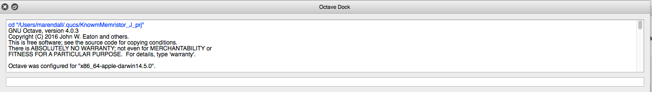
-
Next (2) plot windows should be created by the
Qtplot subsystem.NOTE: These plot windows may not be visible due to the fact that the Qucs-S interface may regain focus. You can switch the window focus to the
octave-guiprocess by using the key sequence Command ⌘-Tab. -
The first plot is the Memristor Resistance vs. the Pulse number.
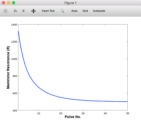
-
The second plot is the Memristor Conductance vs. the Pulse number.
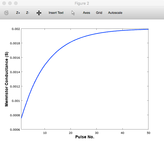
NOTE: The Octave script will require modification to support the JSpice simulation data. The Octave script included in this project works with Xyce simulation data only. Additional features will be added to JSpice in the future that will allow a single Octave script to work with both simulators. More information will be available soon in another blog post. Check back with us for further developments regarding JSpice features.
JSpice is still under development and we will be adding features that are most useful to our mission to provide OSS EDA tools to those of you who are interested in developing neuromorphic circuits using memristor-based synapses. We will be accepting feedback and will be building a wish list for additional requested features for JSpice that may be found in other SPICE compatible simulators. Please leave a comment or send us e-mail through the knowm.org site’s contact page.
|
1 2 |
Please consider joining the KDC `Knowm Developer Community` or become a `Knowm OSS EDA Contributor` to help build out these and other features you would like to see implemented in the tools. |
You should also checkout the documentation and other examples listed in the Qucs 0.0.19 and Qucs-S 0.0.19 documentation available on the web at the following URLs.
References
- Comparing Simulation Results for the Knowm M-MSS Model in Xyce and JSpice Using Qucs-S
- JSpice GitHub repository
- Qucs 0.0.19 Help: https://qucs-help.readthedocs.io/en/0.0.19/subcircuit.html
- Qucs-S 0.0.19 Help: https://qucs-help.readthedocs.io/en/spice4qucs/SPICEComp.html
- Qucs-S Bugtracker: https://github.com/ra3xdh/qucs/issues
- Qucs-S Sub-project Home Webpage: https://ra3xdh.github.io/
General Notes on Usage
Default simulator selection
When selecting a new default simulator, if you want the change to be persistent after closing Qucs-S then you need to do the following steps.
- Select
Simulation->Select default simulator. -
Select the simulator in the
Default simulatordrop-down list. -
Click
Apply changes. -
Select
File->Application Settings. -
Click
Applyto save the settings. -
Click
OKto exit the dialog. -
Select
Qucs->Quit Qucs.NOTE: Several of the features of the Qucs-S user interface are displayed based on the
Default simulatorwhich is saved in theQucsSettingsfile updated when you save theApplication Settingsfor the program. If you don’t perform the steps outlined above before closing Qucs-S then theDefault simulatorselection will not be saved and the will not be set when reopening Qucs-S. This issue should be corrected in a future version of the software.
Other References
- What is Qucs?
- What can all be installed from Sourceforge?
- Qucs Website: http://qucs.sourceforge.net/
- Main Repository: https://sourceforge,net/p/qucs/git/ci/master/tree/
- Mirror Repository: https://github.com/Qucs/qucs
- Mailing lists: http://sourceforge.net/p/qucs/mailman/
- Forum: http://sourceforge.net/p/qucs/discussion/
- Bug trackers:
- Source code documentation:
- Wiki: https://github.com/Qucs/qucs/wiki


Leave a Comment