
Overview
This is the second in a series of posts that I will be publishing to serve as tutorials for using the Knowm OSS EDA Stack to support the design, layout and simulation of memristors and neuro-memristive circuits and devices. This post will cover three additional memristor models which are available in the Known OSS EDA – Xyce-6.6 release candidate 1. The first model is the TEAM model developed by Shahar Kvatinsky, Eby G. Friedman, Aninoam Kolodny and Uri C. Weiser and presented in a paper titled TEAM: ThrEshold Adaptive Memristor Model, published in IEEE Transactions on Circuits and Systems -I: Regular Papers, Vol. 60, No. 1, January 2013. The second model is the Yakopcic model developed at the University of Dayton, by Chris Yakopcic and presented in a paper titled, Memristor Device Modeling and Circuit Design for Read Out Integrated Circuits, Memory Architectures, and Neuromorphic Systems, published in 2014 as part of the requirements for a PhD in Electrical Engineering. The third model is the Joglekar model developed by Biolek et al., published in 2009 titled, SPICE Model of Memristor with Nonlinear Dopant Drift, which decribes the mathematical model of the prototype memristor device manufactured in 2008 at HP Labs. The first two models, TEAM and Yakopcic models were added to the Xyce OpenModels library by the Xyce Team at Sandia National Labs. The third Joglekar model is now available within the Xyce Electronic Simulator’s OpenModels library thanks to Tim Molter of Knowm, Inc., and is featured in his post Native Memristor Device Developement in Xyce, Creating the Joglekar memristor model in Xyce from scratch
Prerequisites
- Please follow the installation and configuration of your Knowm OSS EDA Environment found in the tutorial titled Simulating the Knowm M-MSS Memristor Model Using Qucs-S with Xyce
NOTE: The current release candidate for the Knowm OSS EDA Stack is available for macOS Sierra 10.12 and Ubuntu 16.04 LTS (Xenial Xerus). This post covers installation on MacOS and Linux but usage only on the macOS platform. The installation process is different, but the use of the software is more or less the same. There is currently support for Xyce (Serial) simulations. The included versions of Qucs-S (0.0.19S) and Xyce 6.6 include libraries for amd64 (intel) 64-bit architectures. Support for other architectures and operating systems are under development and will be released when available.
Launch Qucs-S
- Click on the Qucs app icon on the Launcher Bar.
Open a Project File
- Double click the
Ymemristor_prjto automatically open theContenttab.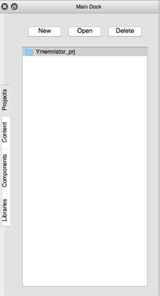
Qucs Project List
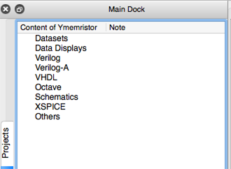
Qucs Project Contents
Create the Schematic diagram
-
Select the
Componentstab in the Main Dock. -
Open the
sourcesfrom the drop down combo box. -
Select the
ac Voltage Sourceand then left click on the schematic to place the symbol. -
Press the
Esckey to exit place mode.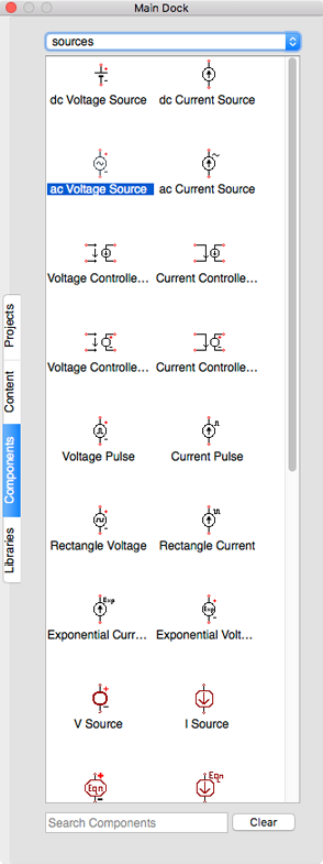
Qucs Component Sources
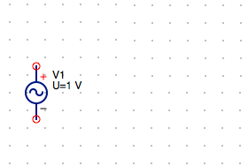
AC Voltage Source
-
Open the
nonlinear componentsfrom the drop down combo box. -
Select the
MR Memristorand then left click on the schematic to place the symbol. -
Press the
Esckey to exit place mode.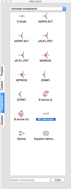
Non-linear Components Selection
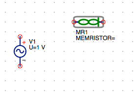
Components MR1 Memristor
-
Open the
probesfrom the drop down combo box. -
Select the
Current Probeand then left click on the schematic to place the symbol. -
Press the
Esckey to exit place mode.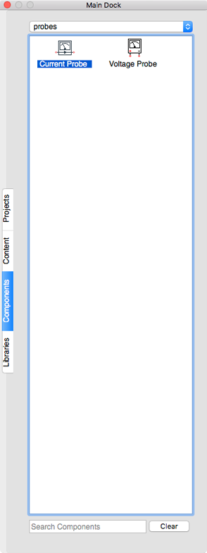
Component Current Probe
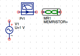
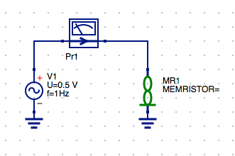
AC Voltage Source, MR1 Memristor and Current Probe
Set AC Voltage Source properties
-
Select the
frow in the properties table. -
Change the
frequencyfrom1 GHzto10 Hz. -
Select the
display in schematiccheckbox.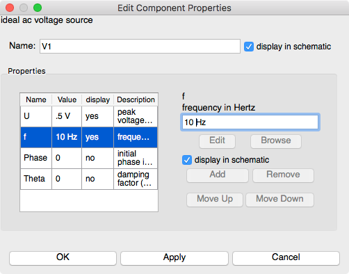
AC Voltage Source Frequency Setting
-
Click
Applyto set the frequency value. -
Click
OKto exit the properties dialog. -
Open the
lumped componentsfrom the drop down combo box. -
Select the
Resistor USand then left click on the schematic to place the symbol.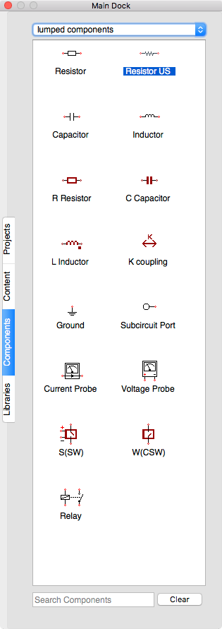
Select Component Resistor US from lumped components
-
Press the
Esckey to exit place mode.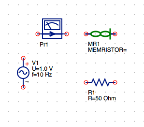
Schematic with All Components
SUGGESTION: Try to place each component’s nodes on the grid. You can either manually position the component using you mouse or right click on the component symbol and select
Set on Grid.
Clean up component and set MR Memristor parameters
-
Click on the
Resistorsymbol and select theRotatebutton on the toolbar or press
Toolbar Rotate Button
Command⌘+Rkeys to orient the resistor symbol with its text to the right. -
Right click on the
MR1 Memristorsymbol and select theRotate or press the Command⌘+Rthree times to orient the memristor with the minus terminal in the down position.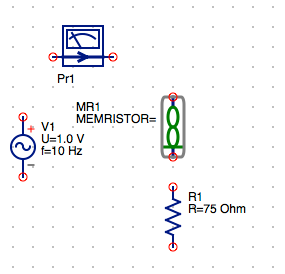
Schematic with R1 and MR1 Rotated
-
Right click again on the
MR1 MemristorsymbolMove Component Textfrom the context menu. -
Left click on the
MR1 MEMERISTORlabel and drag it to a position to the right of the memristor symbol.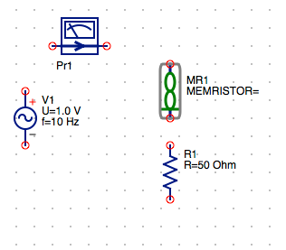
MR1 Component with Repositioned Text
-
Left click anywhere on the schematic to exit
movemode.
Edit the Value of Resistor R1
-
Right click on the
R1 Resistorsymbol and select theEdit Properties.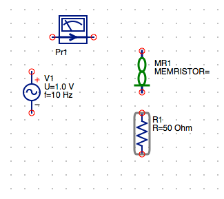
Select R1 to Edit the Properties
-
Select the
Rrow and enter75 Ohms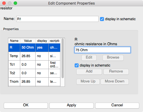
Set R1 Resistance Value
-
Click
Applyto set the frequency value. -
Click
OKto exit the properties dialog.
Place the Ground nodes
-
Select the
Gndsymbol on the toolbar.Then left click on the lower terminal of the
Gnd Toolbar Button
R1 Resistorto place the symbol on the schematic. -
Click on the minus terminal of the
ac Voltage Sourceto place anotherGndsymbol on the schematic. -
Press the
Esckey to exit place mode.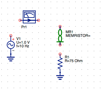
Schematic with Gnd Nodes Added
Wire the Schematic Components
-
Select the
Wiretool button on the toolbar.
Wire Toolbar Button
-
Select the upper terminal of
R1node and then left click the negative node of theMR1memristor symbol. -
Press the
Esckey to exit place mode. -
Select the positive node of the
ac Voltage Sourceand then left click the input node of theCurrent Probe. -
Select the positive node of the
MR1 Memristorand drag to the out node of theCurrent Probe Pr1.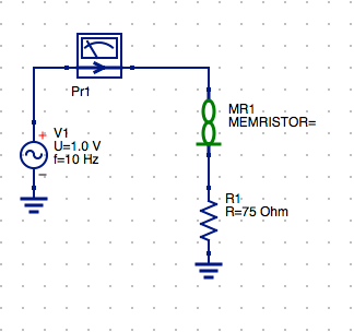
Schematic with All Components Wired
Add a Named Node (Vmr)
-
Click the
Namebutton on the toolbar.
Named Node Toolbar Button
-
Left click on the positive node of the
MR1 Memristorsymbol. -
Enter the
Vmrfor the label.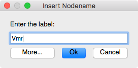
VmrNamed Node -
Click
OKto save the changes. -
Press the
Esckey to exit place mode. -
Click on the
Vmrlabel and drag it to a position below the memristor symbol. -
Left click on the schematic to exit
movemode.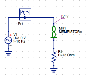
Named Node (Vmr) Set to Retrun Memristor Voltage
Add a Named Node (Vout)
-
Click the
Namebutton on the toolbar.Named Node Toolbar Button
-
Left click on the connection between
R1and the negative node of theMR1 Memristorsymbol. -
Enter the
Voutfor the label.
Add Named Node (Vout)
-
Click
OKto save the changes. -
Press the
Esckey to exit place mode. -
Click on the
Voutlabel and drag it to a position below the memristor symbol. -
Left click on the schematic to exit
movemode.
Named Node (Vout) Set to Return Volts Output
Select .Model Directive for the MR1 Memristor Component
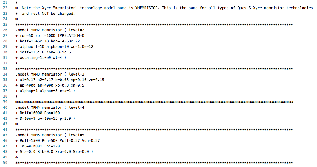
The MR Memeristor model is accompanied by several model directives that can be independently applied to each memristor symbol instance in the schematic diagram. These are selected from the Libraries tab. The MR Memristor component is used for multiple model definitions in Xyce. These are selected by the level parameter of the model. The following levels are available for the MR Memristor model in Xyce.
The parameters sets are stored in the .Model card format for SPICE compatible simulators.
- level=2 : TEAM memristor model
- level=3 : Yakopcic memristor model
- level=4 : Joglekar memristor model
- level=5 : Knowm M-MSS memristor model
Xyce Memristor Technology Lib
NOTE: There are 4 different levels for the Memristor Model in Xyce. Each of these correspond to the model parameter sets above. At this point of this tutorial you can select form any of the available models in the Xyce Memristor Technology Library. The selection .Model and assignment to the MR1 Memristor component in the schematic determines the the model being simulated. There are a few other differences in the circuit design based on the model selected. I will point out the subtle changes to the circuit schematic and explain their significance as we proceed through the rest of this tutorial.
To Select the TEAM Model
- Select the
Librariestab from the Main Dock. -
Left click on the
Xyce_Memristor_Technologyto expand the list. -
Select the appropriate
MRM(X)file for the model you want to use. In this caseMRM2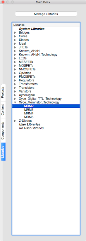
MRM2 for TEAM Model
-
Left click to place the .Model directive on the schematic.
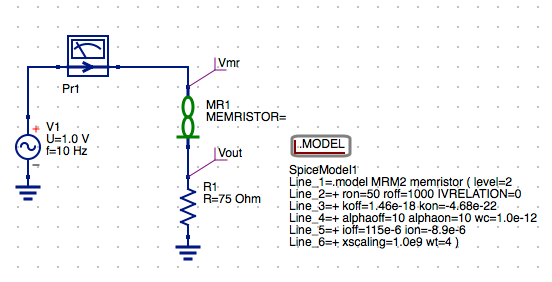
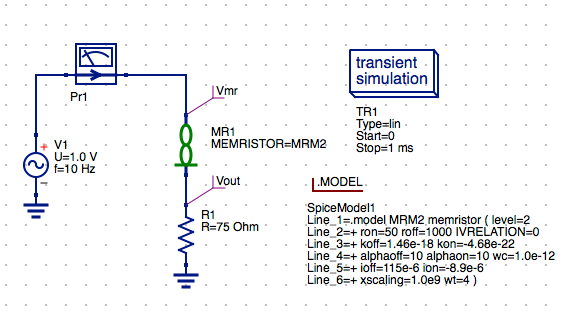
Schematic with TEAM Model
-
Press the
Esckey to exit place mode.
Assign the MRM2 TEAM Model to MR1 Memristor
-
Double click on the
MR1symbol to open the setup parameters dialog. -
Select MEMRISTOR line 1.
-
Enter
MRM2for the TEAM model to assign it to the MR1 Memristor compnent
MR1 Component Set MRM2 to use TEAM Model
-
Click
Applyto save the changes. -
Click
OKto exit the properties dialog.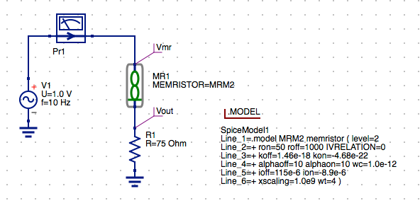
Schematic with MRM2 TEAM Model
Configure the Transient Simulation
-
Select the
Componentstab from the Main Dock. -
Open the
simulationsfrom the drop down combo box. -
Click and drag the
Transient Simulationand drop it on the schematic and left click to place the symbol. -
Press the
Esckey to exit place mode.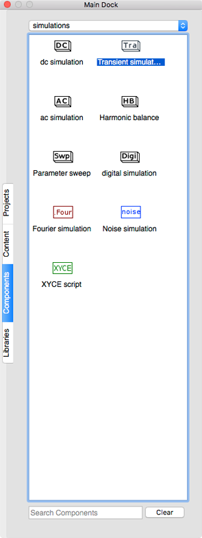
Select Transient simulation
Schematic with Transient Simulation
-
Double click on the
transient simulationsymbol to open the setup parameters dialog.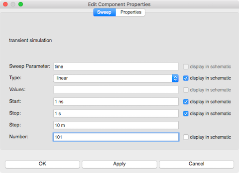
Transient Simulation Settings
-
Enter
1 nsin theStartparam field. -
Enter
1 sin theStopparam field. -
Enter
101in theNumbervalue field to set a 10 ms step size. -
Click
Applyto save the changes. -
Click
OKto exit the properties dialog.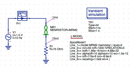
Schematic with Transient Simulation Parameters Set
Save the Schematic Diagram File
-
Click the
Savebutton on the toolbar.
Save Toolbar Button
-
Enter the filename
team_mr_testfor the schematic diagram. -
Click
Saveto save the schematic to the.schfile.
Run a Simulation
-
Press
F2or selectSimulation/Simulatemenu item or click theRunbutton on the toolbar.
Run Simulation Toolbar Button
-
Check simulation for
errorsorwarnings. See the status bar at the bottom of the Qucs windowlower right corner.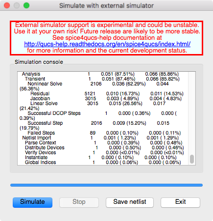
External Simulation Window
-
Click the
Exitbutton to close theSimulationwindow. -
You can view and messages written by the simulator by clicking the
F5key or selectingShow Last Messagesfrom the Simulations menu.
Xyce Message Log
-
You can save the current netlist by clicking the
Save Netlistbutton on the simulation window.NOTE: The
F6key orShow Last Netlistfrom the Simulations menu currently only displays the last netlist for the lastest Qucsator simulation. If you save the netlist using the button on the simulation window then you can open the.cirfile underOtherslist in the project tree.
Qucs-S Generated Netlist
Set Document Settings (Optional)
For smaller sized schematics it is often desirable to add the data tables and plots to the schematic diagram. The default behavior is for the data to displayed in a separate tab after the simulation is complete. You can change this behavior by changing the settings for the schematic diagram.
- Right click on the schematic and select
Document Settings... -
Select
Simulationstab. -
Uncheck
open data display after simulationcheckbox in the dialog.
Document Settings
-
Click
Applyto save the changes. -
Click
OKto exit the properties dialog.
Check Tabular Results
-
Select the
Componentstab from the Main Dock. -
Open the
diagramsfrom the drop down combo box.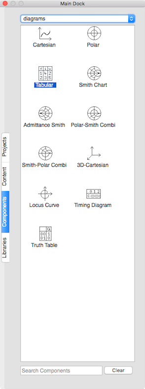
Component Diagram Tabular Data
-
Select the
Tabularand then left click on the schematic to place the table.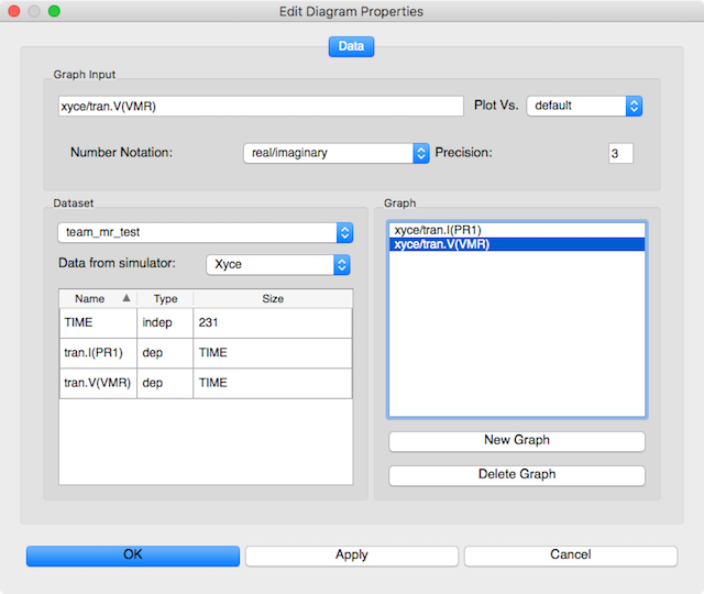
Tabular Diagram Settings
-
Double click on the
tran.I(PR1)row to add it to the graph. -
Double click on the
tran.V(VMR)row to add it to the graph. -
Click
Applyto set the value. -
Click
OKto save the changes.
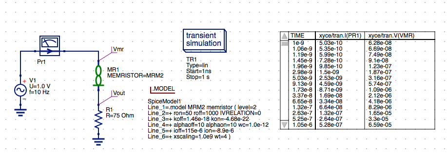
Schematic with Trasient Tabular Results
- Press the
Esckey to exit place mode.
Create a I-V vs. Time Plot
- Select the
Componentstab from the Main Dock. -
Open the
diagramsfrom the drop down combo box. -
Select the
Cartesianand then left click on the schematic to place the symbol.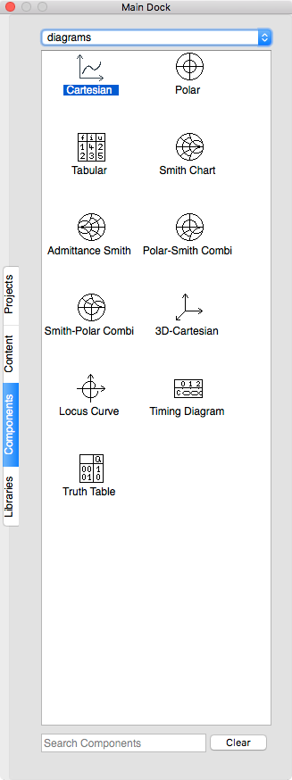
Component Diagram Cartesian Plot
-
Double click
tran.V(VMR)row to add it to the graph.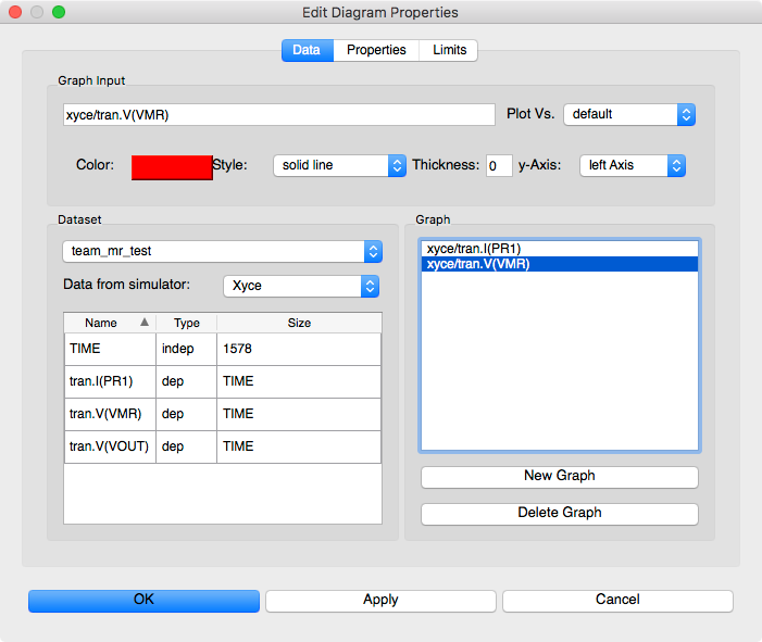
I-V vs Time Plot Settings
-
Double click on the
tran.I(PR1)row to add it to the graph.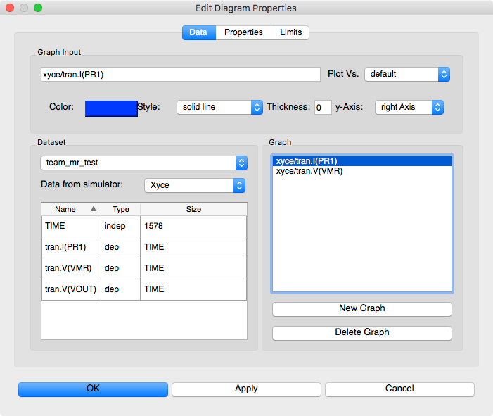
I-V vs Time Plot Settings
-
Select the
tran.I(PR1)in the Graph window and then selectright Axisfrom they-axis:drop-down list.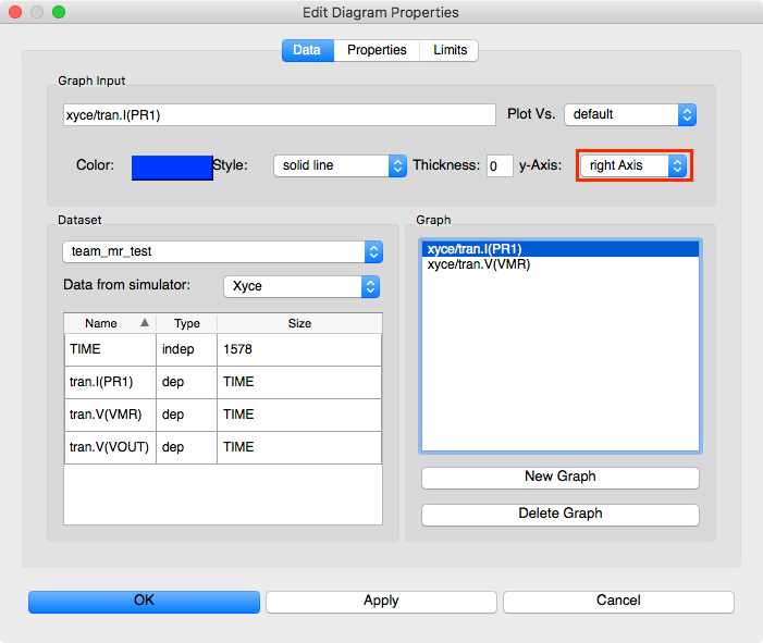
I-V vs Time Plot Settings – PR1 on Y2 Axis
-
Click
Applyto save the changes. -
Click
OKto exit the properties dialog. -
Press the
Esckey to exit place mode. -
Left click anywhere on the plot window and use the corner grab handles to resize the plot.
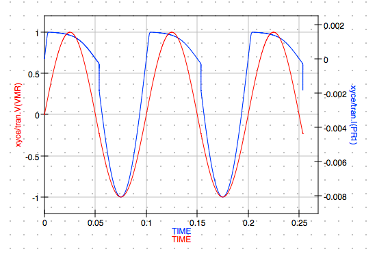
I-V vs Time Plot
Create a Hysteresis Plot
-
Select the
Componentstab from the Main Dock. -
Open the
diagramsfrom the drop down combo box. -
Select the
Cartesianand then left click on the schematic to place the symbol.Component Diagram Cartesian Plot
-
Double click on the
tran.I(PR1)row to add it to the graph.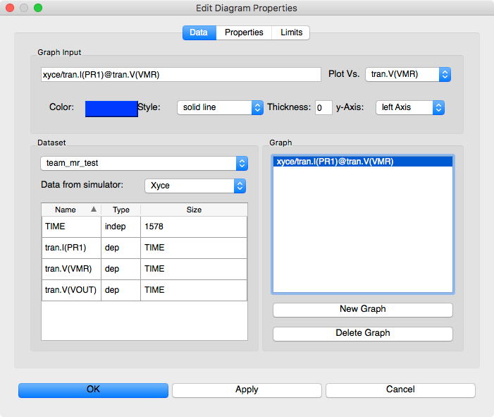
Hysteresis I vs V Setting
-
Select the
tran.I(PR1)in the Graph window. -
Select
tran.V(VMR)in thePlot Vs.dropbox.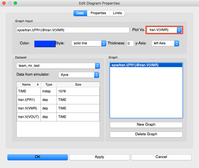
Hysteresis I vs V with Plot vs Set to VMR
-
Click
Applyto save the changes.Notice that the
Graph Inputchanges to xyce/tran.I(PR1)@tran.V(VMR) -
Click
OKto exit the properties dialog. -
Press the
Esckey to exit place mode. -
Left click anywhere on the plot window and use the corner grab handles to resize the plot.
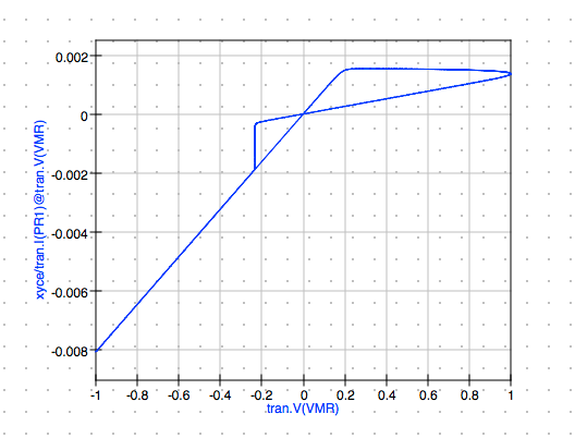
Hysteresis I vs V Plot
Whew! Now you should have project for TEAM Model simulation. Be sure to save your project before continuing.
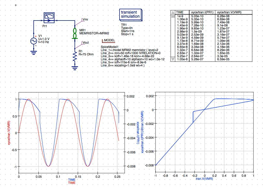
TEAM Model Simulation
Yakopcic Model (Additional Exercise)
Try to create the schematic diagram yakopcic_mr_test.sch on your own. You will need to start from scratch with a new schematic. Use the File/New menu option or click the New toolbar button
New Toolbar Button
When creating your new schematic for the Yakopcic memristor test you can omit the current limiting resistor R1 that was present in the TEAM model test circuit because the Yakopcic model does not require this component in order to perform the transient simulation. This will give you a feel for the model characteristics without the addition of the voltage divider configuration of the TEAM model test circuit.
When you have completed the wired schematic you should have all the components placed and wired. Your schematic should look something like this
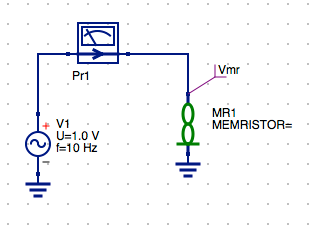
Schematic with All Components Wired and Vmr
To Select the Yakopcic Model
- Select the appropriate
MRM(X)file for the model you want to use. In this caseMRM3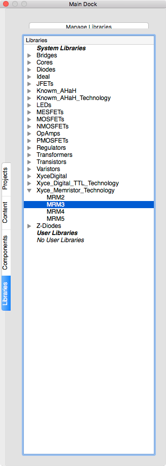
Select MRM3 for Yakopcic Model
-
Left click to place the .Model directive on the schematic.
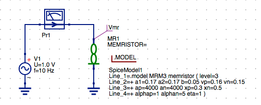
Schematic with .Model MRM3 for Yakopcic Model
-
Press the
Esckey to exit place mode.
Assign the MRM3 Yakopcic Model to MR1 Memristor
-
Double click on the
MR1symbol to open the setup parameters dialog. -
Select MEMRISTOR line 1.
-
Enter
MRM3for the Yakopcic model to assign it to the MR1 Memristor compnent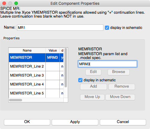
Set MRM3 for Yakopcic Model
-
Click
Applyto save the changes. -
Click
OKto exit the properties dialog.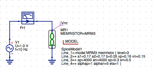
Schematic with MR1 Assignend MRM3 Yakopcic Model
Configure the Transient Simulation
-
Select the
Componentstab from the Main Dock. -
Open the
simulationsfrom the drop down combo box. -
Click and drag the
Transient Simulationand drop it on the schematic and left click to place the symbol. -
Press the
Esckey to exit place mode.Select Transient simulation

Schematic with Transient simulation
-
Double click on the
transient simulationsymbol to open the setup parameters dialog. -
Enter
1 nsin theStartparam field. -
Enter
1 sin theStopparam field. -
Enter
101in theNumbervalue field to set a 10 ms step size.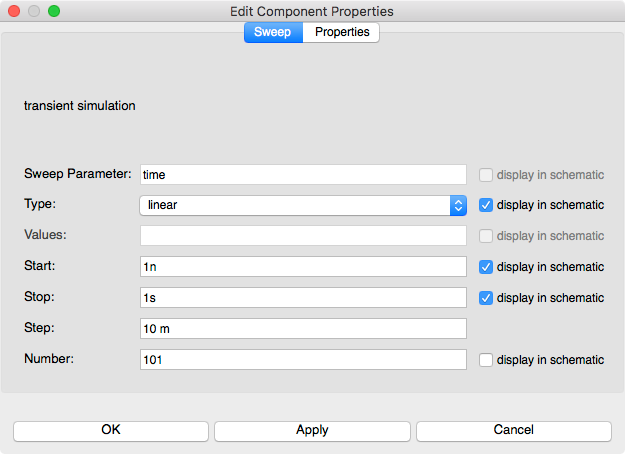
Transient Simulation Settings
-
Click
Applyto save the changes. -
Click
OKto exit the properties dialog.
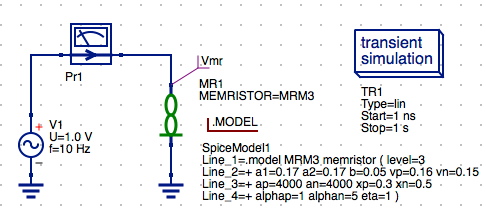
Schematic with Transient Simulation
Save the Schematic Diagram File
-
Click the
Savebutton on the toolbar.Save Toolbar Button
-
Enter the filename
yakopcic_mr_testfor the schematic diagram. -
Click
Saveto save the schematic to the.schfile.
Run a Simulation
-
Press
F2or selectSimulation/Simulatemenu item or click theRunbutton on the toolbar.Run Simulation Toolbar Button
-
Check simulation for
errorsorwarnings. See the status bar at the bottom of the Qucs windowlower right corner.External Simulation Window
-
Click the
Exitbutton to close theSimulationwindow.
Try to reproduce the Tabular and Cartesian Plot setup on your own. You can refer back to the TEAM Memristor section of above if you need a hint. When you have completed this section your schematic should look something like the following image.
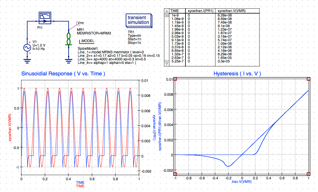
Yakopcic Model Simulation
Joglekar Model (Additional Exercise)
Again try to create the schematic diagram joglekar_mr_test.sch on your own.
For this exercise let’s change the AC Sinusoidal amplitude for this model simulation. To change the voltage of the AC sinusoidal voltage source do the following.
Set AC Voltage Source properties
- Double click on the
ac Voltage Sourcesymbol to open the parameters for the source. -
Select the
Urow in the properties table. -
Change the voltage from
1 Vto500 mV. -
Click
Applyto set the voltage value.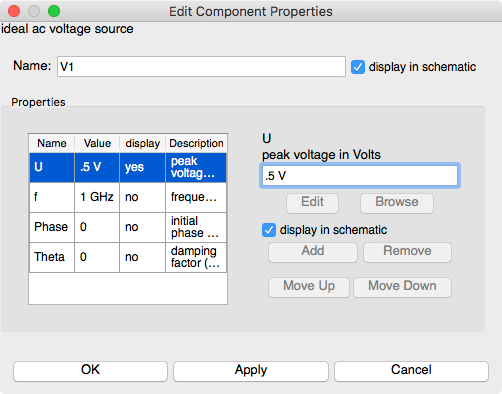
AC Voltage Source Settings
Your schematic should now look something like this:
Complete Wired Schematic
To Select the Joglekar Model
- Double click on the
MR1symbol to open the setup parameters dialog. -
Select MEMRISTOR line 1.
-
Select the appropriate
MRM(X)file for the model you want to use. In this caseMRM4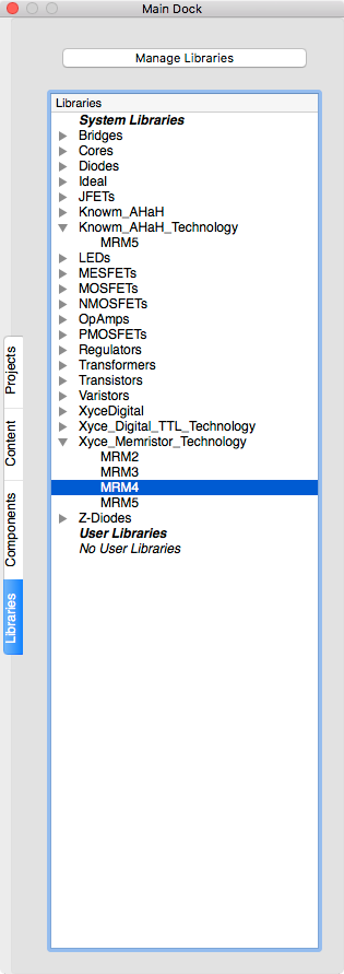
Joglekar model MRM4
Assign the MRM4 Joglekar Model to MR1 Memristor
-
Double click on the
MR1symbol to open the setup parameters dialog. -
Select MEMRISTOR line 1.
-
Enter
MRM4in the param list and model spec field.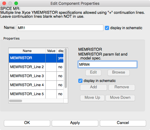
Enter MRM4 for MR1 Memrsitor
-
Click
Applyto save the changes. -
Click
OKto exit the properties dialog.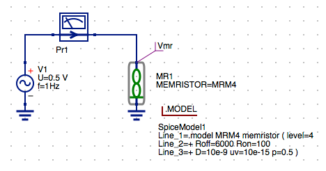
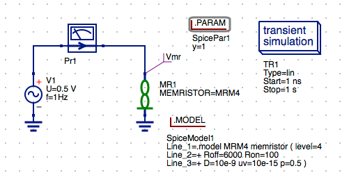
Joglekar model selected for MR1
Configure the Transient Simulation
-
Select the
Componentstab from the Main Dock. -
Open the
simulationsfrom the drop down combo box. -
Click and drag the
Transient Simulationand drop it on the schematic and left click to place the symbol. -
Press the
Esckey to exit place mode.Select Transient simulation
Transient simulation
-
Double click on the
transient simulationsymbol to open the setup parameters dialog. -
Enter
1 nsin theStartparam field. -
Enter
1 sin theStopparam field. -
Enter
101in theNumbervalue field to set a 10 ms step size.
Transient Simulation Parameters
-
Click
Applyto save the changes. -
Click
OKto exit the properties dialog.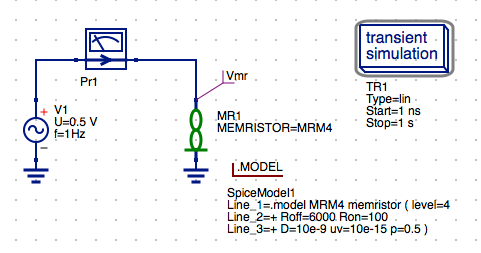
Schematic with Transient simulation
Configure the R_init Parameter for the MR Memristor Model
Like the KnowmMemristor M-MSS model which we looked in our very first tutorial you need to add the .PARAM directive to set the initial resistance R_init for the model. This again can be accomplished by do the following steps.
- Select the
Componentstab from the Main Dock. -
Open the
SPICE specific sectionsfrom the drop down combo box. -
Click and drag the
.PARAM Sectionand drop it on the schematic and left click to place the symbol. -
Press the
Esckey to exit place mode.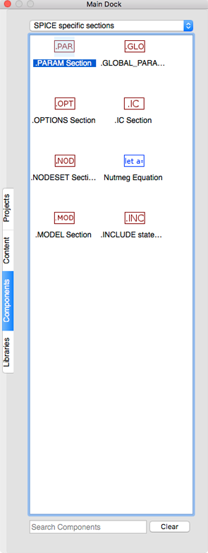
Components SPICE Specific
Schematic with .PARAM
- Double click on the
.PARAMsymbol to open the setup parameters dialog. -
Enter
R_initin the param field. -
Enter
11000in the value field to set R_init=11000 ohms.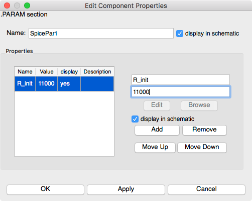
Set R_init to Default Resistance
-
Click
Applyto save the changes. -
Click
OKto exit the properties dialog.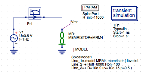
.PARAM R_init set to 11000
Set Document Settings (Optional)
For smaller sized schematics it is often desirable to add the data tables and plots to the schematic diagram. The default behavior is for the data to displayed in a separate tab after the simulation is complete. You can change this behavior by changing the settings for the schematic diagram.
- Right click on the schematic and select
Document Settings... -
Select
Simulationstab. -
Uncheck
open data display after simulationcheckbox in the dialog.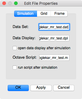
Document Settings
-
Click
Applyto save the changes. -
Click
OKto exit the properties dialog.
Save the Schematic Diagram File
- Click the
Savebutton on the toolbar.
Save Toolbar Button
-
Enter the filename
joglekar_mr_testfor the schematic diagram. -
Click
Saveto save the schematic to the.schfile.
Run a Simulation
-
Press
F2or selectSimulation/Simulatemenu item or click theRunbutton on the toolbar.Run Simulation Toolbar Button
-
Check simulation for
errorsorwarnings. See the status bar at the bottom of the Qucs windowlower right corner.External Simulation Window
-
Click the
Exitbutton to close theSimulationwindow.
Try to reproduce the Tabular and Cartesian Plot setup on your own. You can refer back to the TEAM Memristor section of above if you need a hint. When you have completed this section your schematic should look something like the following image.
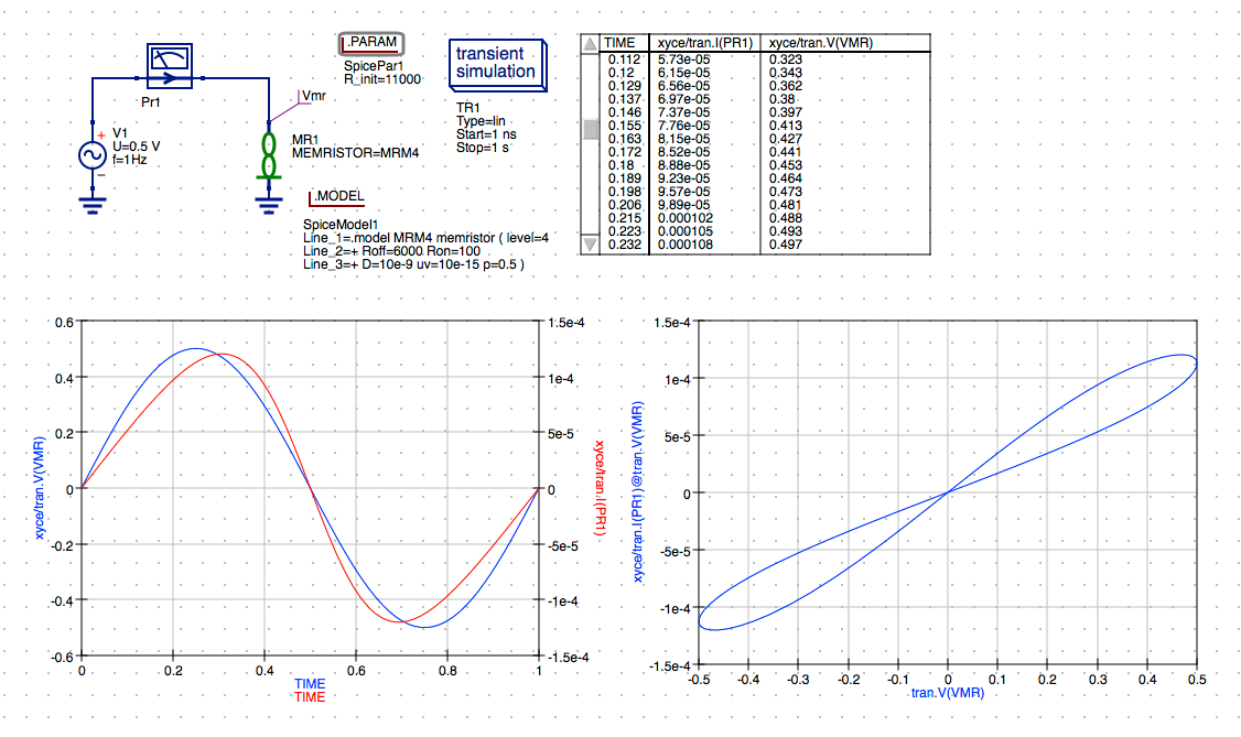
Transient Simulation of Joglekar Model
Conclusion
That completes this three part tutorial. You should also checkout the documentation and other examples listed in the Qucs 0.0.19 and Qucs-S 0.0.19 documentation available on the web at the following URLs. In my next post we will be exploring more dynamic behavior or the Knowm M-MSS Memristor Model with respect to square-wave pulse response by looking at Bi-directional Incremental Conductance Change and other effects.
- Qucs 0.0.19 Help: https://qucs-help.readthedocs.io/en/0.0.19/subcircuit.html
- Qucs-S 0.0.19 Help: https://qucs-help.readthedocs.io/en/spice4qucs/SPICEComp.html
- Qucs-S Bugtracker: https://github.com/ra3xdh/qucs/issues
- Qucs-S Sub-project Home Webpage: https://ra3xdh.github.io/
Other References
- What is Qucs?
- What can all be installed from Sourceforge?
- Qucs Website: http://qucs.sourceforge.net/
- Main Repository: https://sourceforge,net/p/qucs/git/ci/master/tree/
- Mirror Repository: https://github.com/Qucs/qucs
- Mailing lists: http://sourceforge.net/p/qucs/mailman/
- Forum: http://sourceforge.net/p/qucs/discussion/
- Bug trackers:
- Source code documentation:
- Wiki: https://github.com/Qucs/qucs/wiki
Further Resources
- Knowm Memristors
- The Generalized Metastable Switch Memristor Model
- Simulating the Knowm M-MSS Memristor Model Using Qucs-S with Xyce
- The Problem is Not HP’s Memristor–It’s How They Want To Use It
- The Joglekar Resistance Switch Memristor Model in LTSpice
- Build Xyce from Source for ADMS Verilog-A Model Integration
- The Pershin Voltage Threshold Memristor Model in NGSpice
- memristor-models-4-all Project on Github


Leave a Comment