In 2013, Pershin et al. published a paper showing an idealized memristor model for a device that changes it’s conductance as a function of the applied voltage. The paper can be downloaded here. This blog post is about taking the model from the paper and getting the classic memristor hysteresis I-V plot in NGSpice. It just so happens that the source code for NGSpice contains this model, so it’s really easy to get it working. These concepts can be adapted for different SPICE simulators and models. In addition we show the steps for installing NGSpice and simulating the memristor, compiling the latest NGSpice from source, and building ADMS into NGSpice for later Verilog-A integration with NGSpice. While these instructions are targeted towards a computer running MacOS and a packaging tool called homebrew, the steps should be similar to other systems such as Windows or Linux.
Install NGSpice the Simple Way
I’m using a Mac so I installed it via homebrew. See latest Ngspice Formula for more info.
|
1 2 |
brew install ngspice --with-x11 |
Install NGSpice the Hard Way – Compile from Source
Dependencies with Homebrew
|
1 2 3 |
brew update brew install flex bison git |
Install Autotools
|
1 2 |
brew install autoconf automake autogen libtool readline |
NGSpice Dependencies with ADMS Support
ADMS is a code generator that converts electrical compact device models specified in high-level description language into ready-to-compile C code for the API of SPICE simulators. Based on transformations specified in XML language, ADMS transforms Verilog-AMS code into other target languages.
Building ADMS with Autotools will require some further Perl modules
|
1 2 |
brew install gd |
Install into system-wide Perl
|
1 2 |
sudo cpan -f GD |
Let’s assume we have a directory for installing all the EDA tools called ~/workspaces/workspace_eda.
|
1 2 3 4 5 6 7 8 9 |
cd ~/workspaces/workspace_eda git clone https://github.com/Qucs/ADMS.git ADMS cd ADMS ./bootstrap.sh ./configure --enable-maintainer-mode sudo make install admsXml -v |
Clone the NGSpice Git repository
NOTE: we will be using the ‘ngspice (experimental)’ branch for supporting experimental features.
To install NGSpice, we will clone the source code and build it.
|
1 2 3 |
cd ~/workspaces/workspace_eda git clone http://git.code.sf.net/p/ngspice/ngspice ngspice |
Build NGSpice with advanced features using Autotools
|
1 2 3 4 5 6 7 |
cd ngspice ./autogen.sh --adms ./configure --with-x --disable-debug --enable-xspice --enable-cider --enable-adms --with-editline=yes make sudo make install ngspice --version |
Build Flags
A full list of build flags can be found in the NGSPICE Manual on page 577.
–enable-adms ADMS is an experimental model compiler that translates Verilog-A compact
models into C code that can be compiled into ngspice. This is still experimental, but working
with some limitations to the models (e.g. no noise models). If you want to use it, please refer
to the ADMS section on ngspice web site.
–with-readline=yes Enable GNU readline support for the command line interface. Gives you command line history.
–with-x enables graphical environment
–enable-xspice Enable XSPICE enhancements, yielding a mixed signal simulator integrated
into ngspice with codemodel dynamic loading support. See chapter 12 and section II
for details
–enable-cider Cider is a mixed-level simulator that couples Spice3 and DSIM to simulate
devices from their technological parameters. This part of the simulator is not compiled by
default.
Run HelloWorld Circuits
To quickly test NGSpice, we can run both a simple DC OP simulation and a simple transient analysis. First, create two files with the following text and save them somewhere on your hard drive.
helloworldop.cir
|
1 2 3 4 5 6 7 8 9 10 11 12 13 |
*A simple Voltage divider V1 1 0 DC 15 R1 1 2 10k R2 2 0 5k .OP .control PRINT v(2) .endc .END |
helloworldtran.cir
|
1 2 3 4 5 6 7 8 9 10 11 12 13 |
* A simple RC Circuit r1 1 2 1k c1 2 0 10n v1 1 0 SIN(0 10 10kHz) .control tran 1u 1000u plot v(1) v(2) .endc .end |
Run the Simulations
|
1 2 3 4 5 |
ngspice cd /path/.../with/cir/files source helloworldop.cir source helloworldtran.cir |
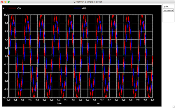
NGSpice Transient Response
Memristor Simulation with NGSpice
The following code can be found on the memristor-models-4-all project.
The Ngspice source code, which can be downloaded here, contains a memristor simulation in ngspice/examples/memristor/memristor.sp. The following code snippet shows the memristor simulation file.
|
1 2 3 4 5 6 7 8 9 10 11 12 13 14 15 16 17 18 19 20 21 22 23 24 25 26 27 28 29 30 31 32 33 34 35 36 37 38 39 40 41 42 43 |
Memristor with threshold * Y. V. Pershin, M. Di Ventra: "SPICE model of memristive devices with threshold", * arXiv:1204.2600v1 [physics.comp-ph] 12 Apr 2012, * http://arxiv.org/pdf/1204.2600.pdf * Parameter selection and plotting by * Holger Vogt 2012 .param stime=10n .param vmax = 3 * send parameters to the .control section .csparam stime={stime} .csparam vmax={vmax} Xmem 1 0 memristor * triangular sweep (you have to adapt the parameters to 'alter' command in the .control section) *V1 1 0 DC 0 PWL(0 0 '0.25*stime' 'vmax' '0.5*stime' 0 '0.75*stime' '-vmax' 'stime' 0) * sinusoidal sweep V1 0 1 DC 0 sin(0 'vmax' '1/stime') * memristor model with limits and threshold * "artificial" parameters alpha, beta, and vt. beta and vt adapted to basic programming frequency * just to obtain nice results! * You have to care for the physics and set real values! .subckt memristor plus minus PARAMS: Ron=1K Roff=10K Rinit=7.0K alpha=0 beta=20e3/stime Vt=1.6 Bx 0 x I='((f1(V(plus)-V(minus))> 0) && (V(x) < Roff)) ? {f1(V(plus)-V(minus))}: ((((f1(V(plus)-V(minus)) < 0) && (V(x)>Ron)) ? {f1(V(plus)-V(minus))}: 0)) ' Vx x x1 dc 0 Cx x1 0 1 IC={Rinit} Rmem plus minus r={V(x)} .func f1(y)={beta*y+0.5*(alpha-beta)*(abs(y+Vt)-abs(y-Vt))} .ends * transient simulation same programming voltage but rising frequencies .control *** first simulation *** * approx. 100 simulation points let deltime = stime/100 tran $&deltime $&stime uic plot i(v1) vs v(1) .endc .end |
Similar to a previously simulated memristor in LTSPICE using the Joglekar nonlinear drift window function, this simulation uses more or less the same concepts, but the exact model and implementation with SPICE sub-components is slightly different. There is also some syntax changes compared to LTSpice. Running the simulation produces the following plot.
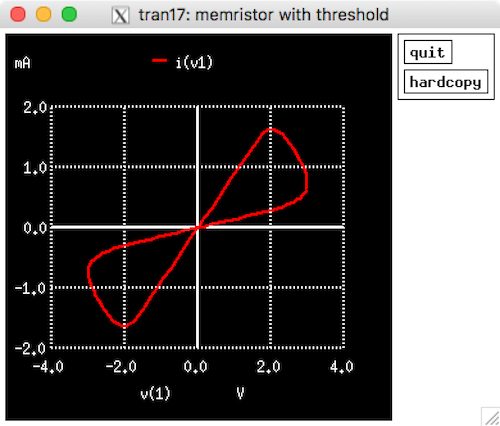
NGSpice Memristor Hysteresis
The resulting I-V plot shows the familiar pinched hysteresis loop response of the memristor in response to a sinusoidal input.
NGSpice Links
- What is Ngspice?
- What can all be installed from Sourceforge?
- Ngspice Website: http://ngspice.sourceforge.net/
- Main Repository: https://sourceforge.net/projects/ngspice/files/ng-spice-rework/
- Mirror Repository: https://sourceforge.net/p/ngspice/ngspice/ci/master/tree/
- Mailing lists: https://sourceforge.net/p/ngspice/mailman/
- Forum: https://sourceforge.net/p/ngspice/discussion/
- Bug trackers:
- Source code documentation:
- Wiki: https://sourceforge.net/p/ngspice/wiki/Home/
Further Resources
- Knowm Memristors
- The Generalized Metastable Switch Memristor Model
- The Problem is Not HP’s Memristor–It’s How They Want To Use It
- The Joglekar Resistance Switch Memristor Model in LTSpice
- memristor-models-4-all Project on Github
- Build Xyce from Source for ADMS Verilog-A Model Integration
- Well-posed Memristor Modeling with Xyce and Verilog-A









Leave a Comment