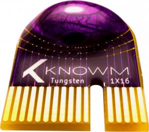
 Ever since Knowm Inc. first launched the BS-AF-W memristors, it became clear that we needed a low-cost programmable interface to make it easier for people to learn how memristors work. Memristors are strange. They are ‘born’, they live for awhile, and they die. If driven too hard the can fry or get stuck. Their behavior is dependent on their history, by design of course, which makes understanding how they work more complicated compared to traditional electronic elements. Probing memristors requires specialized equipment. The lab from which they are created contain very large and expensive pieces of equipment that most people do not have the money (or time) to use. What we needed is a low-cost USB board that allows anybody to experiment with memristors via their own computers. So we set out to find such a board, if it existed. This post is a quick comparison of what we found.
Signal Generation
Signal generators, also known as function generators, RF and microwave signal generators, pitch generators, arbitrary waveform generators, digital pattern generators or frequency generators, are electronic devices that generate repeating or non-repeating electronic signals (in either the analog or digital domains). In our case we need to drive our memristors with various types of modulated signals. Since Knowm Memristor are polar, we ideally need a differential voltage. Some of the devices require forming, a procedure where a voltage is increased until the conductive channels form. When used in series with resistor, we must provide sufficient voltage to overcome the forward and reverse threshold. A differential voltage source of +/- 5 Volts would be ideal.
| Device | Rate | Range | Channels | Steps Size | Notes | Price |
|---|---|---|---|---|---|---|
| RED PITAYA | 125 Msps | ±1 V | 2 | Linux, Zync FPGA, Open Source, Manual, SPI, IIC | $300 | |
| PicoScope 2206A | 1 MHz | ±2 V | 2 | Cross platform Oscilloscope Software, Forum | $319 | |
| Analog Discovery 2 | 100 MS/s | ±5 | 2 | Cross platform | $279 | |
| Smart Scope | 50 MS/s | 0 – 3.3 V | 1 | 13 mV | $229 | |
| Bit Scope | 40 MSPS | 2 | $165 | |||
| SparkFun MiniGen – Pro Mini Signal Generator Shield | 0 – 3.3 V | 1 | Chip 1 Datasheet, Chip2 Datasheet | $30 | ||
| MSO19 | 100 MS/s | 0 – 3.3 V | $249 | |||
| HS5-110 | 100 MS/s | 0 – 3.3 V | $249 |
Data Acquisition
For our needs we require 100 MS/s, a standard API, and at least 2 channels. Some of these on the list were found at the page USB Oscilloscopes from Pro to Hobbyist.
| Device | Sample Rate | Range | Sensitivity | Channels | API | Notes | Price |
|---|---|---|---|---|---|---|---|
| RED PITAYA | 125 Msps | ±20 V | 2 | C, Linux | Linux, Zync FPGA, Open Source, Manual, SPI, IIC | $300 | |
| PicoScope 2206A | 500 Msps | ±20 V | 2 | C SDK for Linux | Forum | $319 | |
| Analog Discovery 2 | 100 Msps | ±25 V | 2 | C, About, Manual | Cross Platform | $279 | |
| Smart Scope | 100 MS/s | 2 | C#, Visual Studio | $229 | |||
| Bit Scope | 40 MS/s | ±11.8V | 1mV to 40mV | 2 | BitScope Library, C, C++, Python and Pascal | $165 | |
| Oscium | 50 MS/s | 2 | no API | iPad only, Manual | $399 | ||
| National Instruments | 100 Msps | ±20 V | 156 mV | 2 | Not open source, windows required | $1420 | |
| Link Instruments MSO-28 | 200 Msps | ±20 V | 1.25 mV | 2 | DLL ($100) | Multi-platform App | $325 |
| Link Instruments MSO-19 | 200 Msps | ±20 V | 2 | no API | Windows Only | $249 | |
| Tie PieHS5-110 | 100 Msps | ±20 V | 2 | LibTiePie SDK, C | Multi-platform App | $1060 | |
| Analog Arts SA935 | 100 Msps | ±8 V | 2 | no API | Windows Only | $300 | |
| Quant Asylum QA101 | 200 Msps | ±50 V | 2 | .NET | Windows Only | $2599 |
Top 3 Contenders
After narrowing down the USB oscilloscope devices options filtering out devices that won’t work, or would work only in a limited fashion, there are three products that remained.
| Spec | RED PITAYA | PicoScope 2206A | Analog Discovery 2 |
|---|---|---|---|
| Price | $300 | $319 | $279 |
| API | C | C | C |
| App | Cross platform | Cross platform | Cross platform |
| Input Channels | 2 | 2 | 2 |
| Output Channels | 2 | 2 | 2 |
| Power Supplies | 0 | 0 | 2 |
| ADC/DAC res | 14 bit | 12 bit | 14 bit |
| Probes Included | 2 | 2 | 0 |
| Product Manual | Link | Link | Link |
| SDK Manual | Link | Link | Link |
| Software Manual | Link | Link | Link |
| USB | 2.0 | ||
| Main Chip | Xilinx Zynq 7010 | ||
| Output Range | ±1 V | ±2 V | ±5 V |
| Input Range | ±20 V | ±20 V | ±25 V |
| Input Rate | 125 MS/s | 500 MS/s | 100 MS/s |
| Output Frequency (square wave) | 10 MHz | 1 MHz | 10 MHz |
| Country | Slovenia | UK | USA |
| Single Pulses | Y | Y | Y |
| ADC | LTC2145-14 | AD9648 | |
| DAC | AD9767 | AD9717 | |
| External Trigger-able | N (Internally) | Y | Y |
Red Pitaya and Analog Discovery 2 First Impressions
We decided to go with the Red Pitaya and Analog Discovery 2, try out both of them and see which one ends up being the best. The PicoScope seemed to be a bit cluncky compared to the other two and the support people wouldn’t tell us what A2D and D2A chips were in the device. Both USB oscilloscopes have different pluses and minuses and we’re honestly not 100% sure of their capabilities given the information on-line, so we decided to purchase them and try them out for ourselves.
Both units arrived in less than a week from time of order.
Analog Discovery 2
FedEx called because of the wrong address on the Analog Discovery 2, which delayed the shipment by two days.
The packaging of the Analog Discovery 2 was very clean and professional. We unpacked it, hooked up the probes, downloaded and installed the software. The software download included two components: the app and an FTDI driver for the Analog Discovery 2. After starting the app, the device was not at all recognized. After restarting the computer and trying again, the software connected to the device. The app was intuitive and worked flawlessly, and we were able to successfully take some measurements.
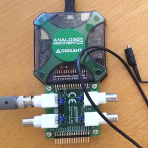
Analog Discovery 2 with BNC Adapter Board
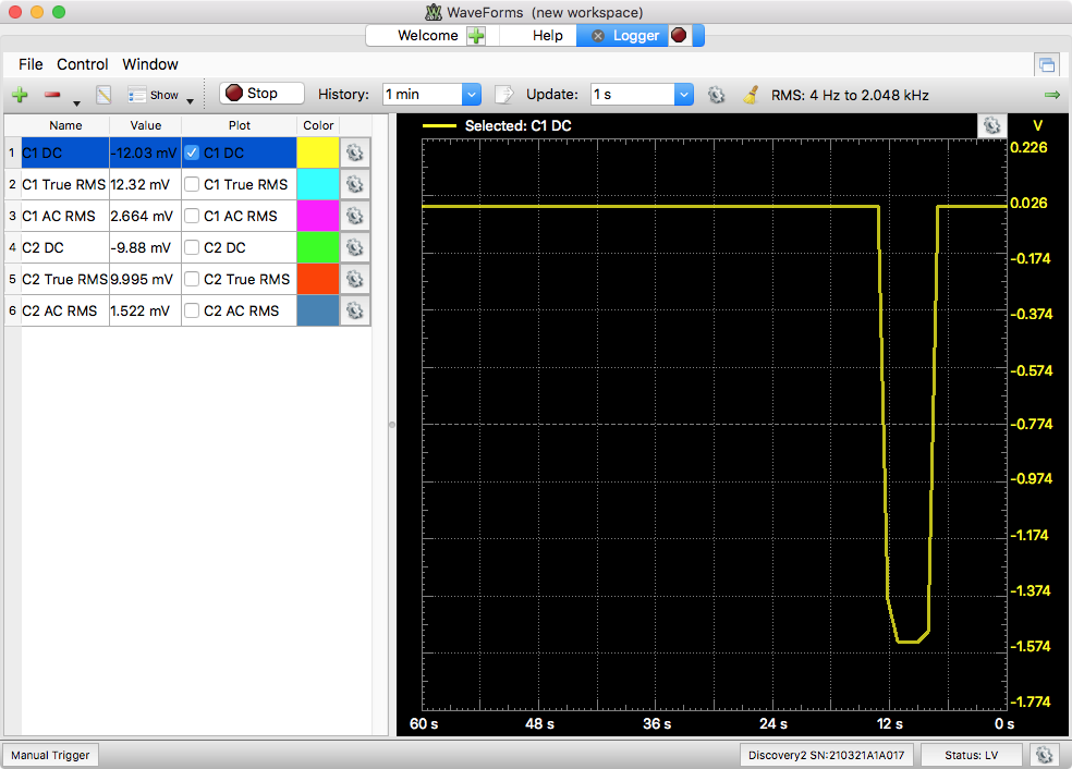
Digilent Waveforms Software
The BNC Adapter Board for the Analog Discovery provides a convenient interface for I/O via 4 BNC connectors. The two outputs have jumpers to select 50 Ohm coupling if desired. The two input have jumpers for AC or DC coupling. There is a schematic for the jumpers, which comes in handy. The standoffs underneath the Adapter board are too long though and make the oscilloscope and I/O adapter not sit flatly on the table.
Red Pitaya
We had to email them four days after the order was placed to see if they got the payment. We got confirmation of item shipped shortly thereafter. The packaging of the Red Pitaya was also very clean and professional, however the seal on the inner box containing the device was broken as was the inner plastic bag around the device. A card was found with the device which indicated we should visit www.redpitaya.com/turniton to get started. The first thing we needed to do was download the SD card image and install it. This involved downloading separate software called ApplePi-Baker. Unfortunately the process of writing the SD card didn’t work as the instructions said. We first needed to run Preps for NOOBS to first prepare the SD card. Before that, we just saw a message: waiting for recipe, and we really had no idea what the issue was. We suspect that this step was already run on the SD card since it looks like this product was already opened. Was this a previous return item perhaps?
Continuing on with their ‘getting started’ instructions, we plugged in the device to LAN and power and noticed the blinking lights indicating proper function. Using their device discovery tool based on the MAC address of the device didn’t work however nor did running arp -a in the terminal as suggested. I ended up looking at the DHCP table in my router to find the device’s IP address. Luckily at this point everything was working. We used their web app to install the free oscilloscope app and do a test measurement. About a week later, we received a Wifi dongle to use with the Red Pitaya. Setup worked flawlessly following the quick-start instructions exactly, choosing the “connect wirelessly” option. Note that you must restart the Red Pitaya twice like it says. The auto-discovery tool also worked.
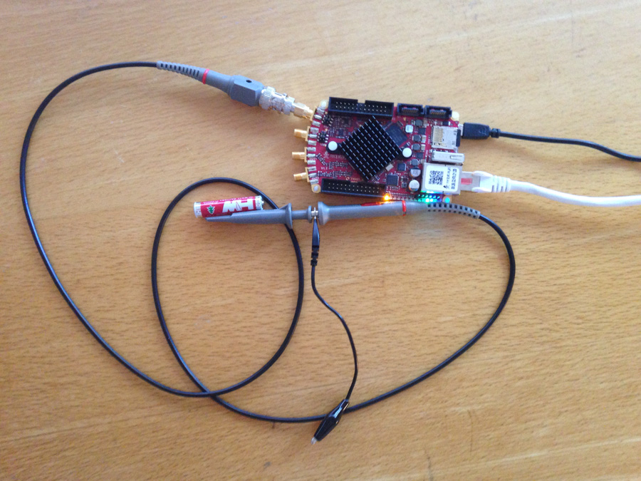
Red Pitaya Board
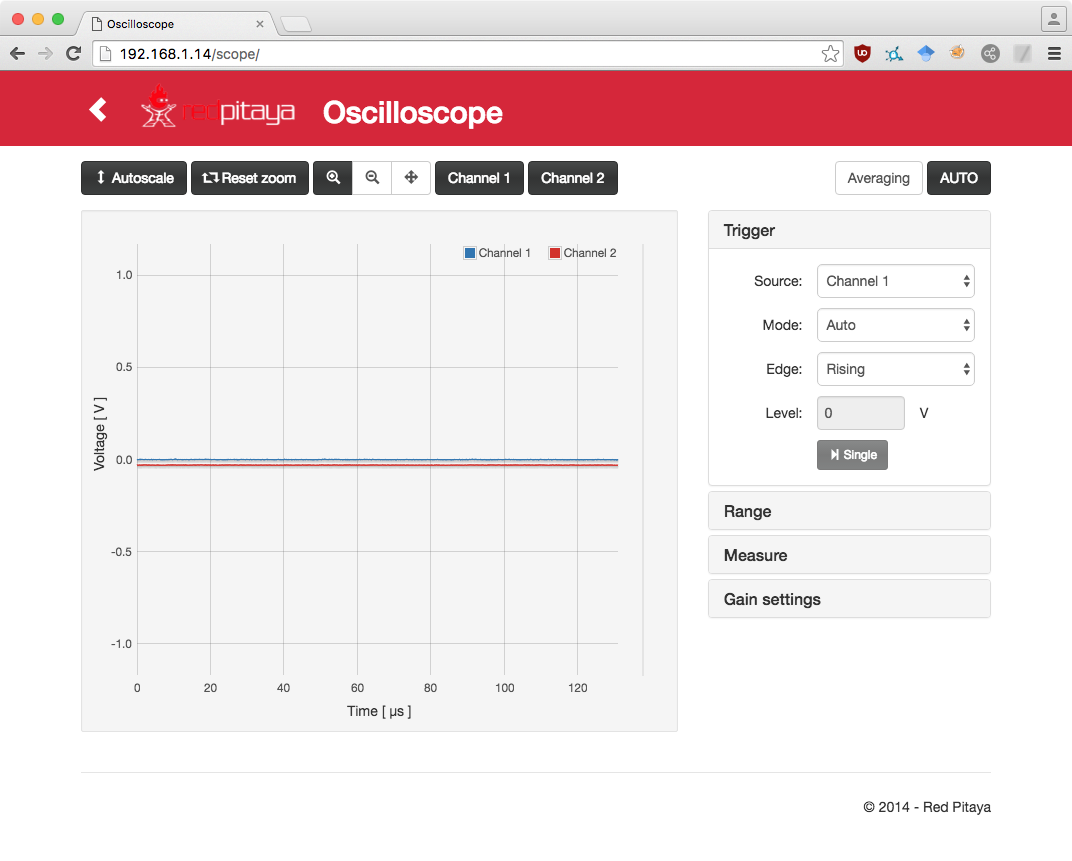
Red Pitaya Software
The extra plastic case that we purchased required assembly. Two of the screws for the bottom plate didn’t seat into the standoff threads even after repeated attempts. This didn’t allow for the screws to go all the way in and prevented the case from sitting flat on all four rubber feet. The 4 I/O connectors are SMA type connectors. The kit we purchased came with 2 SMA to BNC connectors so unfortunately we needed to order two more.
Red Pitaya and Analog Discovery 2 In-depth Comparison of Features
Arbitrary Waveform Generator (Winner = Analog Discovery)
The Red Pitaya was designed for RF applications. Because of this, the AWG outputs have a 50 Ohm resistor in series hard wired and when driving a load, you are supposed to take this into consideration and compensate your loads to be 50 Ohms. More info can be found at this link.
As a general rule, pulse generators with rise times of 2 ns or less must be used with 50 Ohm loads. They will not operate properly with non-50-Ohm loads. The datasheets for these instruments will note that the expected load is 50 Ohms. In some moderately-fast situations, these instruments can still be used with non-50-Ohm loads if series or shunt resistance is added to the load to change the overall effective load resistance to 50 Ohms. However, for the very fastest applications (tR ≤ 100 ps), a proper high-bandwidth 50 Ohm load is required.
Here’s another discussion about this.
The output circuit has a 50 ohm series termination, so when the output is terminated into 50 ohms, forms a voltage divider that drops half of the output voltage across the 50 ohm load and the other half across the internal series resistor. If you are working at lower frequencies and are not impacted by the very high frequency ringing that can occur on the fast transitions of a square wave, then using a load that is higher than the recommended 50 ohms can give you as much as double the output voltage.
The AD2 can also operate at those frequencies, but provides better flexibility as the BNC breakout board has a jumper to let you select this.
Forum and Help (Winner = Analog Discovery)
Both USB oscilloscopes have a forum where questions can be asked. So far we’ve asked a few questions on both forums. The Analog Discovery Forum so far has had the best responses, always very quick to answer.
Full-scale Oscilloscope Input (Winner = Analog Discovery)
Both Oscilloscopes have input voltage ranges that can span the entire 14-bit A2D resolution. The Red Pitaya has a jumper and the Analog Discovery has a software switch. The ranges are however different.
| Device | Low Range | High Range |
|---|---|---|
| Red Pitaya | +/-1 V | +/-20 V |
| AD2 | +/-5 V | +/-25 V |
Full-scale Oscilloscope Output (Winner = Analog Discovery)
Both Oscilloscopes have output voltage ranges that can span the entire 14-bit A2D resolution. The Red Pitaya has a jumper and the Analog Discovery has a software switch. The ranges are however different.
| Device | Low Range | High Range |
|---|---|---|
| Red Pitaya | +/-1 V | N/A |
| AD2 | +/-1 V | +/-5 V |
Digital IO (Winner = Equivalent)
Both have 16 digital I/O pins. The logic levels for the Red Pitaya are 3.3 V and for the AD2 as well.
Power Supplies (Winner = Analog Discovery)
Both provide power supplies. The AD2 has two programmable power supplies (0…+5V , 0…-5V). The maximum available output current and power depend on the Analog Discovery 2 powering choice: 1) 250mW max for each supply or 500mW total when powered through USB and 2) 700mA max or 2.1W max for each supply when using an external wall power supply. The Red Pitaya has 3 power supplies: +5 V, -3.3 V (50 mA) and +3.3 V. The power limit is not documented besides the -3.3 V source.
Other I/O (Winner = Red Pitaya)
The Red Pitaya has a lot of extra I/O options that the AD2 doesn’t have: Analog I/O, SPI, IIC, UART, etc. They both have external triggers.
Programming API (Winner = Analog Discovery)
The Red Pitaya API works through a couple different layers: Client <-> Nginx server via JSON GETs and POSTs (websockets too?), NGINX <-> Red Pitaya Nginx module, to Red Pitaya Nginx module <-> C -controller. In order to transfer any signals or get/set any parameters, the controller.so application specific code (the mandatory functions) needs to read or write to some FPGA registers, respectively or it can perform any other application specific action. Full documentation can be found on their Github page and a forum entry has a nice overview.
The web applications are simple HTML and Javascript files served by Nginx. The plots are Flot plots, which we are familiar with.
There is a potential problem with the API and triggering that could affect us in a bad way: source.
The WaveForms system is comprised of multiple components as defined in the Analog Discovery 2 SDK Manual. The most visible component is the WaveForms Application; a suite of graphical instrument panels that give full access to the analog and digital instruments in the connected hardware. The WaveForms application uses the WaveForms Runtime to control all signal generation and acquisition. The WaveForms Runtime is comprised of the DWF Dynamic Library and several configuration files. In order to develop an application with this SDK, we would probably create a Java bridge using JNI and either make a Java Swing GUI app or a web app.
Update: We did create a Java Wrapper for the Waveforms SDK: waveforms4j and a Java Swing app: Memristor-Discovery!
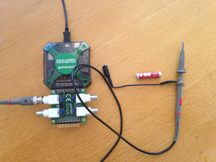
Viewing I-V Curves (Winner = Analog Discovery)
In order to demonstrate a hysteresis loop for a memristor, we need to be able to plot I-V curves, and this is something we can test out really quickly using a resistor of known resistance. The test setup includes driving a triangle wave across the resistor and measuring the voltage across the resistor with one oscilloscope channel. A virtual channel needs to be converted to a current by a simple division of the first channel’s voltage by the resistor value. Then the signal is plotted as an X-Y curve. This first experiment will show us the capabilities and limitations of the two chosen oscilloscopes.
Analog Discovery 2
Setting this up was extremely simple. When we needed a hint, the “Help” tab came in handy and explained what we needed: 1) how to setup a virtual “Math” channel (M1) where we divided the voltage of channel 1 by the resistor value and 2) How to add an X-Y plot.
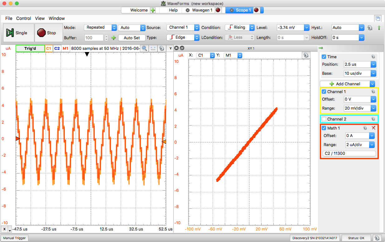
Analog Discovery Waveforms IV Plot
Replacing the resistor with a Knowm Memristor:
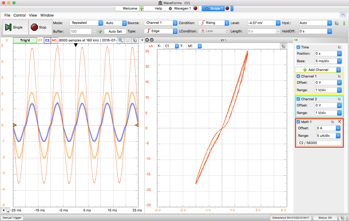
Analog Discover 2 Waveforms Software IV Memristor Hysteresis
Red Pitaya
With the Red Pitaya and the free software it comes with, it’s not possible to produce an X-Y plot.
Overall Winner = Analog Discovery 2
Based on the above, we decided to go with the Analog Discovery 2 (AD2) and make a custom board and software for it. We used digital I/O from the AD2 to drive some switches to select memristors. The addition of some probe points, a few resistors and a beefy DIP socket and we have our first generation `Memristor Discovery Board’. The SDK came with C and Python APIs, but not a Java API as we would have preferred. However, given the C API and Java JNI, creating a Java API was not too difficult. We have open sourced our Waveforms4J Java SDK for the AD2 if anyone is interested.
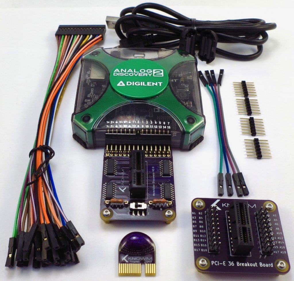
Memristor Discovery V2 Kit

4 Comments
Johan
Good introductions to usb oscilloscope. i have used this one http://fanyit.com/review/hantek-best-usb-oscilloscope-review/ just for hobby i’m not a professional in this. Some one to tell me more about this scope.
Kaitlyn
The ability to communicate with SPI, I2C, and UART, was added to the Analog Discovery 2 in one of the most recent versions of WaveForms 2015. Now the IO is a bit more expansive.
Leonhard Neuhaus
If you try downloading my Red Pitaya application PyRPL (www.pyrpl.org), I would expect – based on your report – that you will conclude with Red Pitaya as the winner. The Red Pitaya ecosystem – due to its open source character – is much more vast than it might appear from a first look, so knowing the right application to download is a challenge. However, the reward is a much better and much more flexible device than the AD2.
+1 for publishing the source code of all AD2 applications!
Red Pitaya and Analog Discovery 2… How Do They Compare? – Digilent Blog
[…] First a little background. KNOWM.org is working on developing a new computational framework, to reduce the size and power consumption of machine learning applications. The base of these systems are memristors. Last year Tim Molter and Alex Nugent from KNOWM, began the search for a low-cost interface for people to learn how memristors work. As part of this process they compared a bunch of different USB Oscilloscopes with Software Development Kits(SDKs.) […]